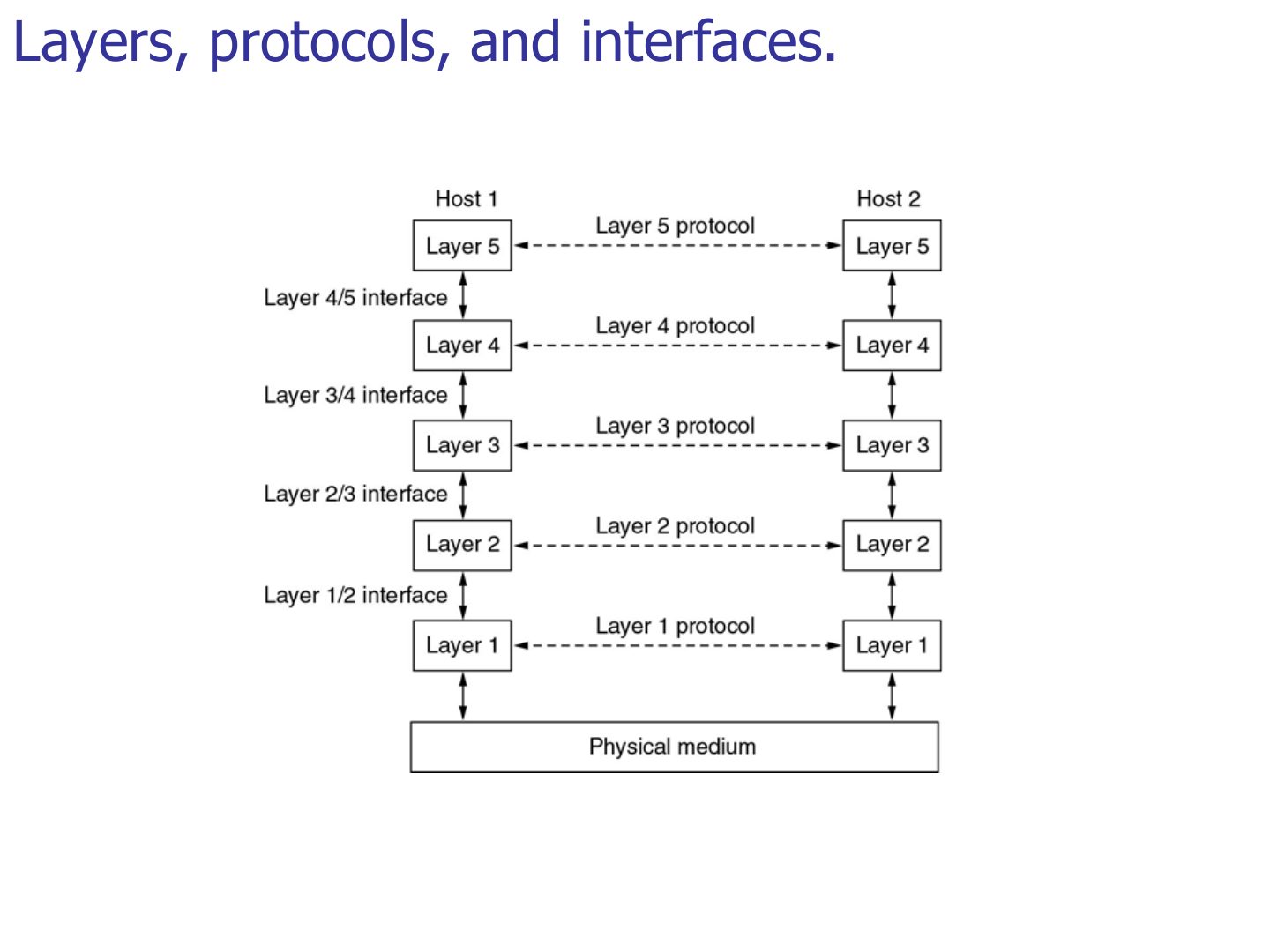
The boundary between two adjacent layers is called a(n):
Introduction: Protocol Layering, TCP/IP and the OSI Model
Why networks are built in layers, the 7 OSI layers and what each one does, its PDU and its address, how encapsulation wraps data on the way down and unwraps it on the way up, and how the 5-layer TCP/IP suite maps onto OSI. Every later chapter is one of these layers, so this deck is the map for the rest of the course.
How to read this page
Every original slide is shown unchanged. Yellow marks on a slide point to a numbered note: hover or tap a mark to jump to its note, and hover a note to see its marks. Questions tagged Past exam appeared on a real paper; Prediction questions are likely angles, not confirmed. Pick an answer to each question: a wrong pick tells you why it is wrong, so you can try again.
All 54 slides
- 1 Introduction
- 2 Chapter 1-Part 2: Outline
- 3 Protocol Layers and Service Models
- 4 Layers, protocols, and interfaces
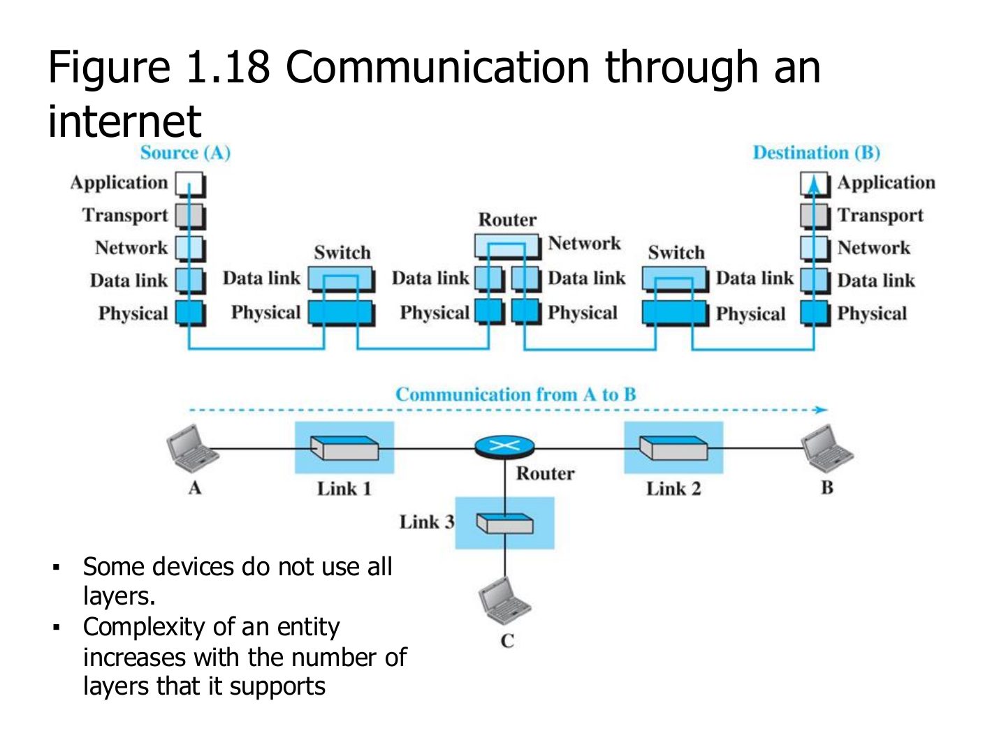
- 5 Communication through an internet
- 6 Advantages of Layered Architecture
- 7 Standard Protocol Models
- 8 OSI Model
- 9 OSI Model
- 10 OSI Model
- 11 OSI Protocols Implementation
- 12 Peer-to-Peer Processes
- 13 OSI model-Basic Operation
- 14 An exchange using the OSI model (Figure 2.4)
- 15 Data Encapsulation
- 16 Decapsulation
- 17 How Hosts Talk over a Network
- 18 How Hosts Talk over a Network
- 19 How Hosts Talk over a Network
- 20 How Hosts Talk over a Network
- 21 How Hosts Talk over a Network
- 22 How Hosts Talk over a Network
- 23 How Hosts Talk over a Network
- 24 How Hosts Talk over a Network
- 25 Physical Layer
- 26 Physical Layer
- 27 RJ-45 connector
- 28 Data Link Layer
- 29 Note: data link layer
- 30 Data Link Layer
- 31 Node-to-node delivery (Figure 2.7)
- 32 Example 1 (Figure 2.8)
- 33 Network Layer
- 34 Note: network layer
- 35 Network Layer
- 36 Source-to-destination delivery (Figure 2.10)
- 37 Example 2 (Figure 2.11)
- 38 Transport Layer
- 39 Note: transport layer
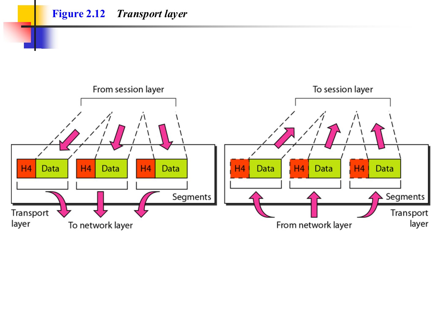
- 40 Reliable process-to-process delivery of a message (Figure 2.12)
- 41 Transport layer (Figure 2.12)
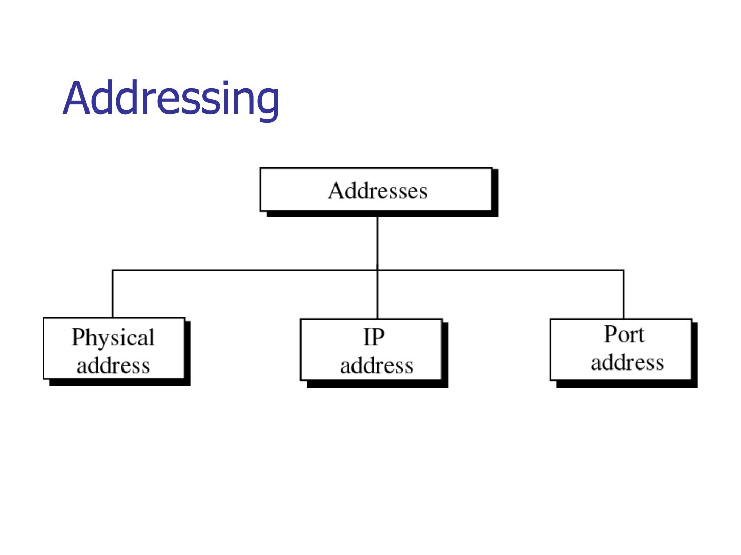
- 42 Addressing
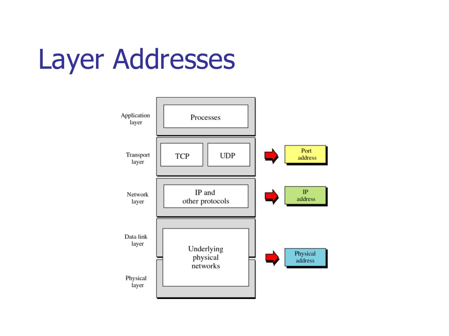
- 43 Layer Addresses
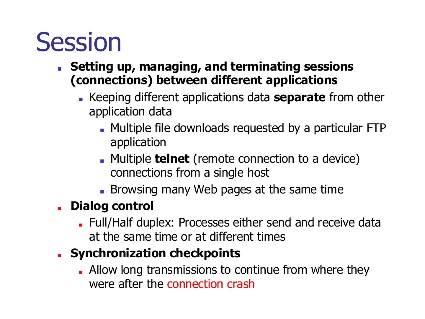
- 44 Session
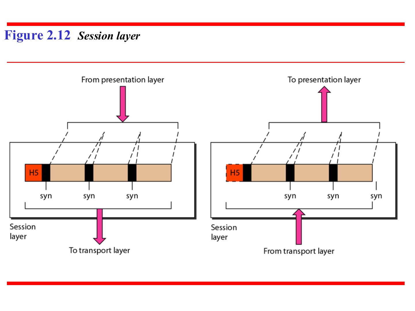
- 45 Session layer (Figure 2.12)
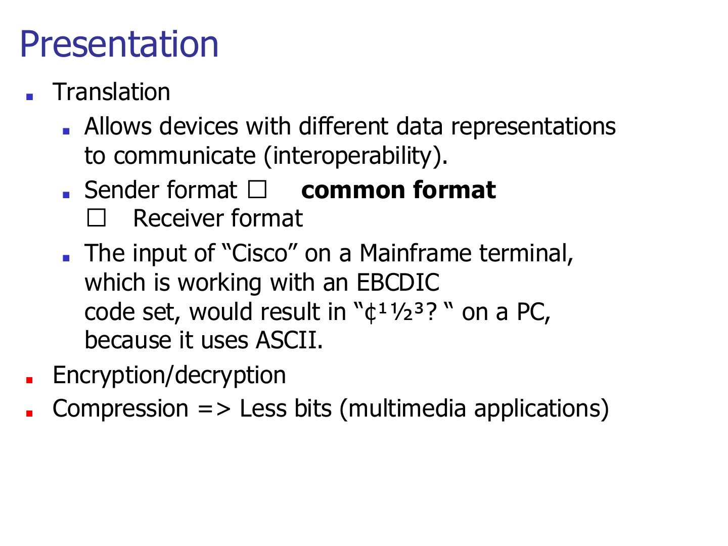
- 46 Presentation
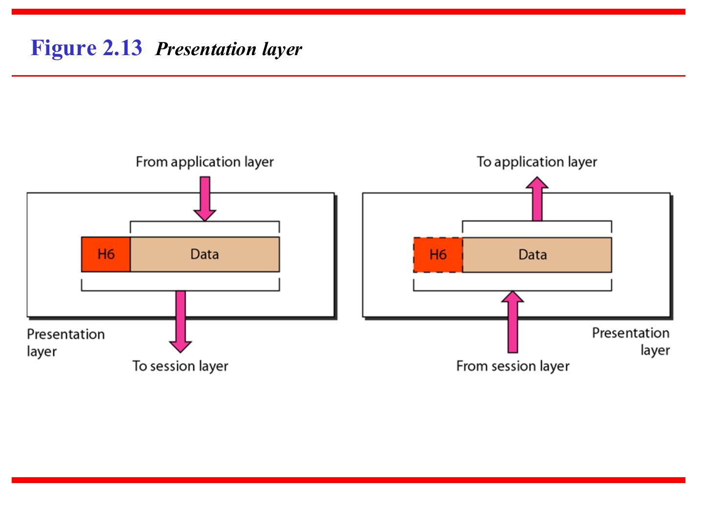
- 47 Presentation layer (Figure 2.13)
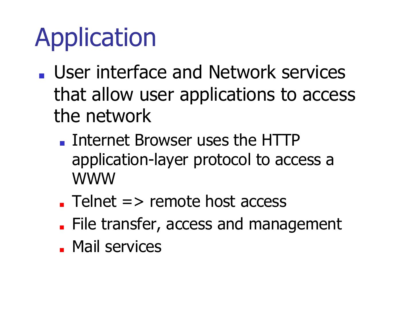
- 48 Application
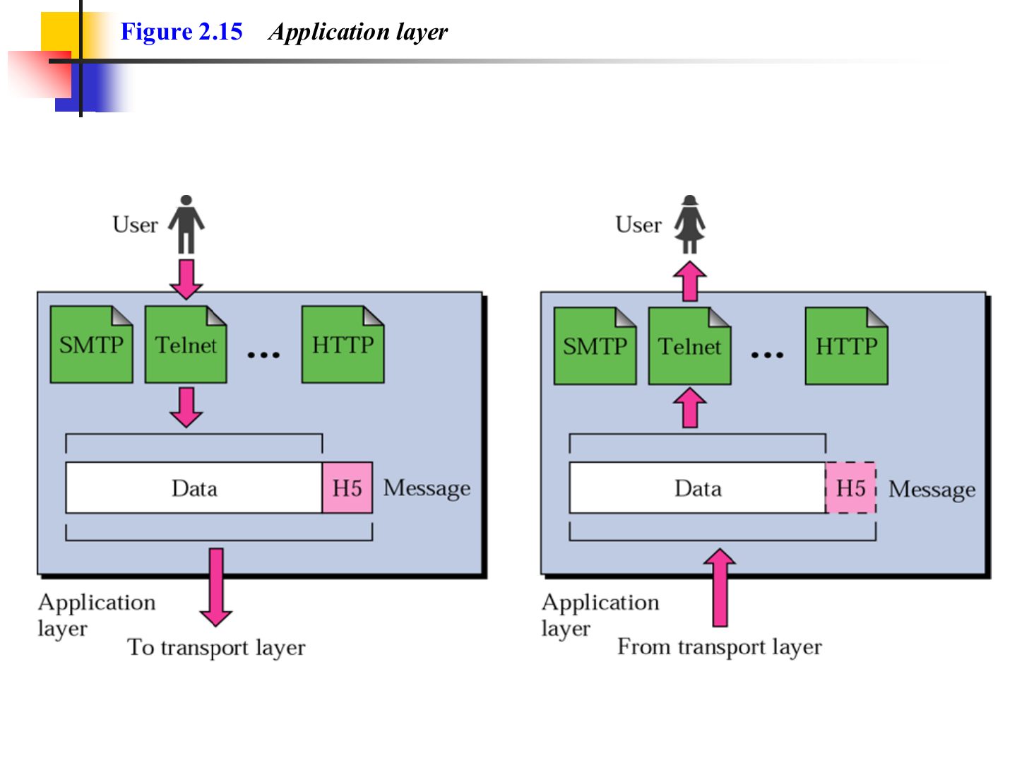
- 49 Application layer (Figure 2.15)
- 50 TCP/IP Protocol Suite
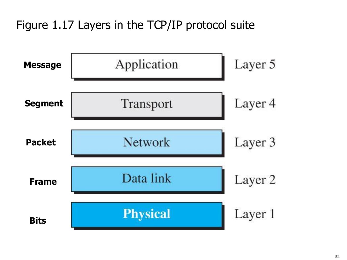
- 51 Layers in the TCP/IP protocol suite (Figure 1.17)
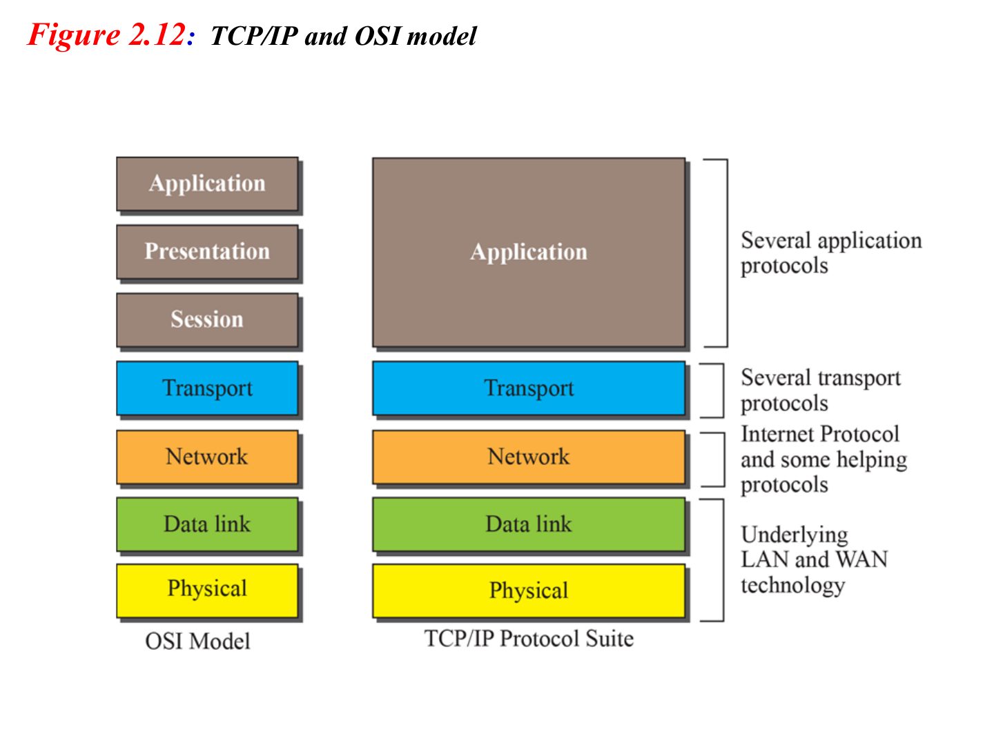
- 52 TCP/IP and OSI model
- 53 TCP/IP and OSI model: protocols
- 54 Original TCP/IP Model (4-layers)
Introduction
Notes
Layering → OSI (7 layers) → encapsulation → each layer’s job, PDU and address → TCP/IP (5 layers).
Memorize the layer table on slide 51: it is used in every chapter after this.
Chapter 1-Part 2: Outline
Protocol Layers and Service Models
Notes
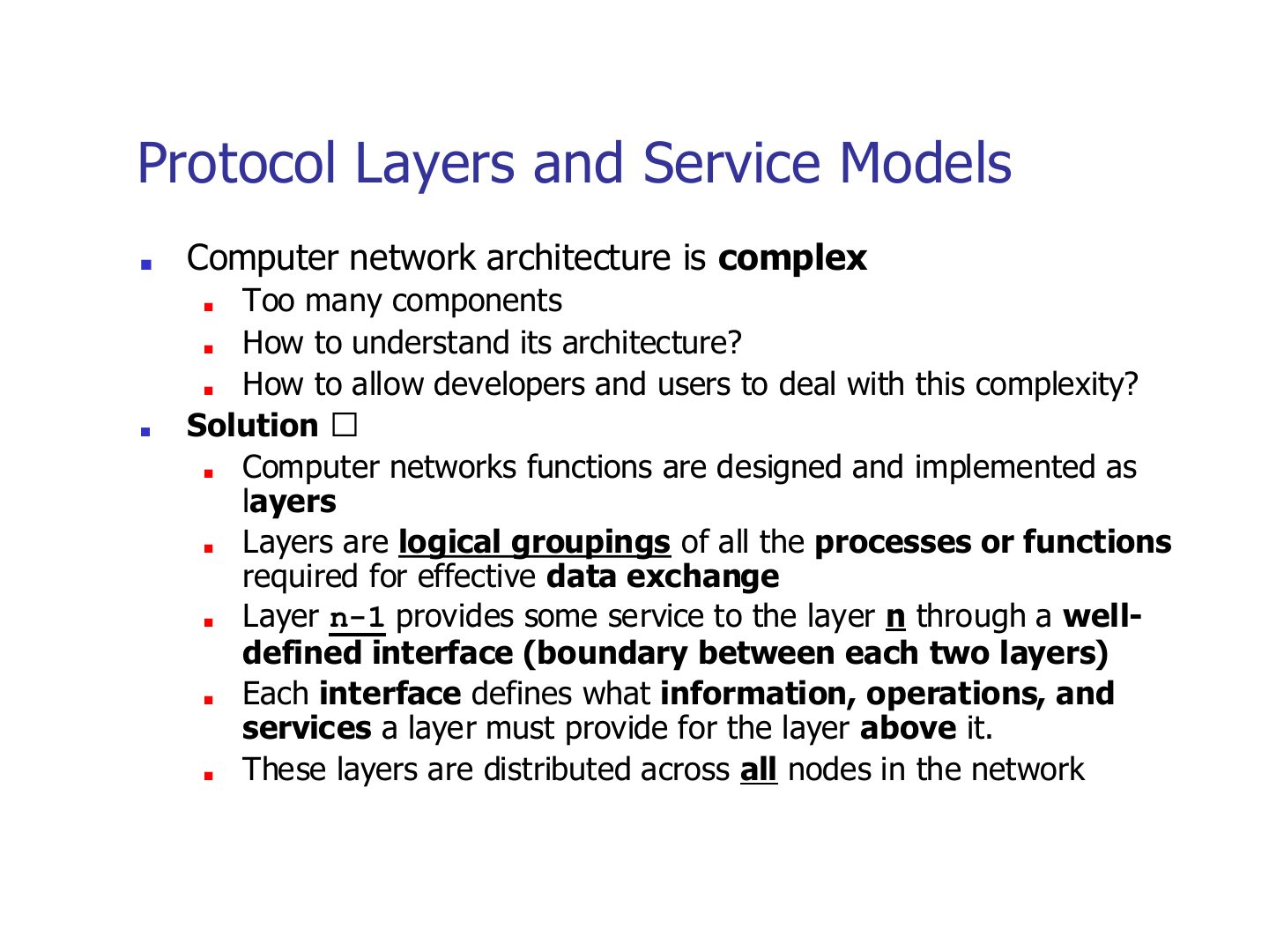
Problem: networks are too complex to understand or build as one piece.
Memory trick A layer only talks to the one directly above and below it on the same machine.
Exam angle
In a layered architecture, layer n-1 provides a service to layer n.
Layers, protocols, and interfaces
Notes
Horizontal = protocol (layer 3 talks to the other host’s layer 3). Vertical = interface.
Only layer 1 actually touches the physical medium; everything above is logical communication.
Trap Protocol ≠ interface. A protocol is between peers on different machines; an interface is between neighbours on the same machine.
Exam angle
Rules used between the same layer on two different hosts are a:
Communication through an internet
Notes
Hosts use all 5 layers. A switch only needs layers 1–2. A router needs layers 1–3.
Seen again Ch 6, slide 3: Which layer each connecting device works at
Exam angle
Up to which layer does a router operate?
A link-layer switch uses which layers?
Advantages of Layered Architecture
Notes
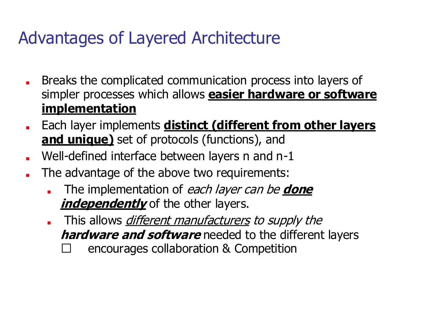
Each layer has its own unique protocols and a well-defined interface → each layer can be built independently.
So different vendors can build different layers (NIC maker, OS maker, browser maker) and it still works.
Exam angle
Give two advantages of a layered network architecture.
Compare with the model answer
It breaks a complex process into simpler pieces, so hardware and software are easier to build. And because each layer has its own protocols and a fixed interface, layers can be built independently by different manufacturers, which encourages collaboration and competition.
Standard Protocol Models
Notes
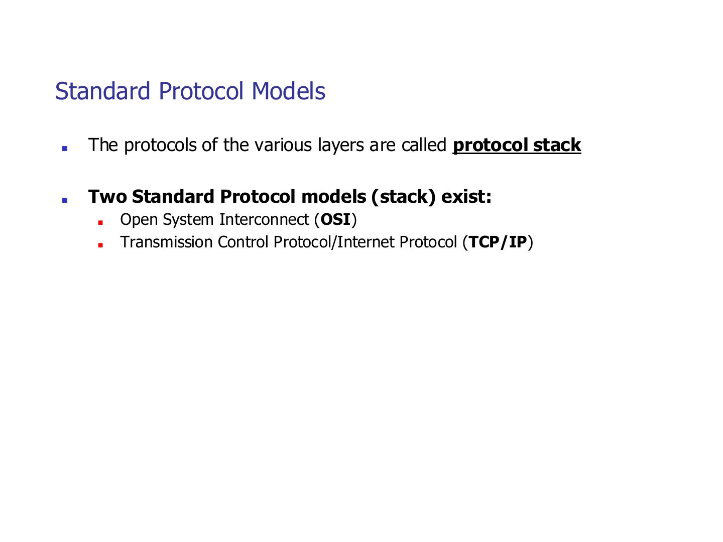
Two standard stacks: OSI (the reference model) and TCP/IP (what the Internet actually runs).
OSI Model
Notes
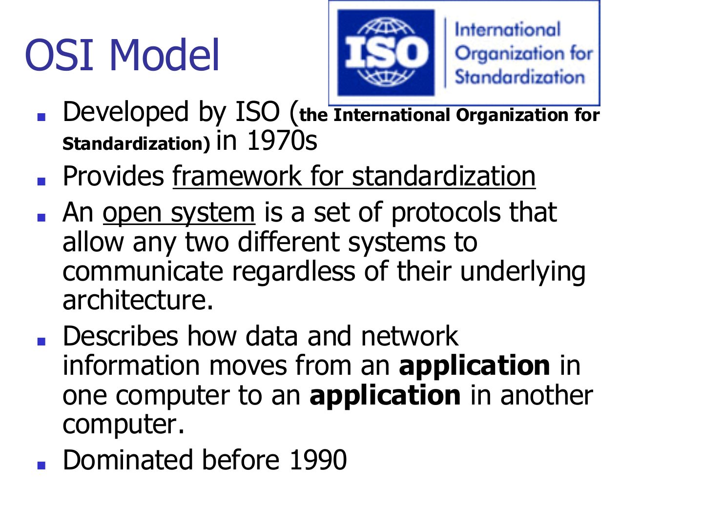
Trap ISO is the organization, OSI is the model. Exam options often swap them.
Exam angle
The OSI model was developed by:
OSI Model
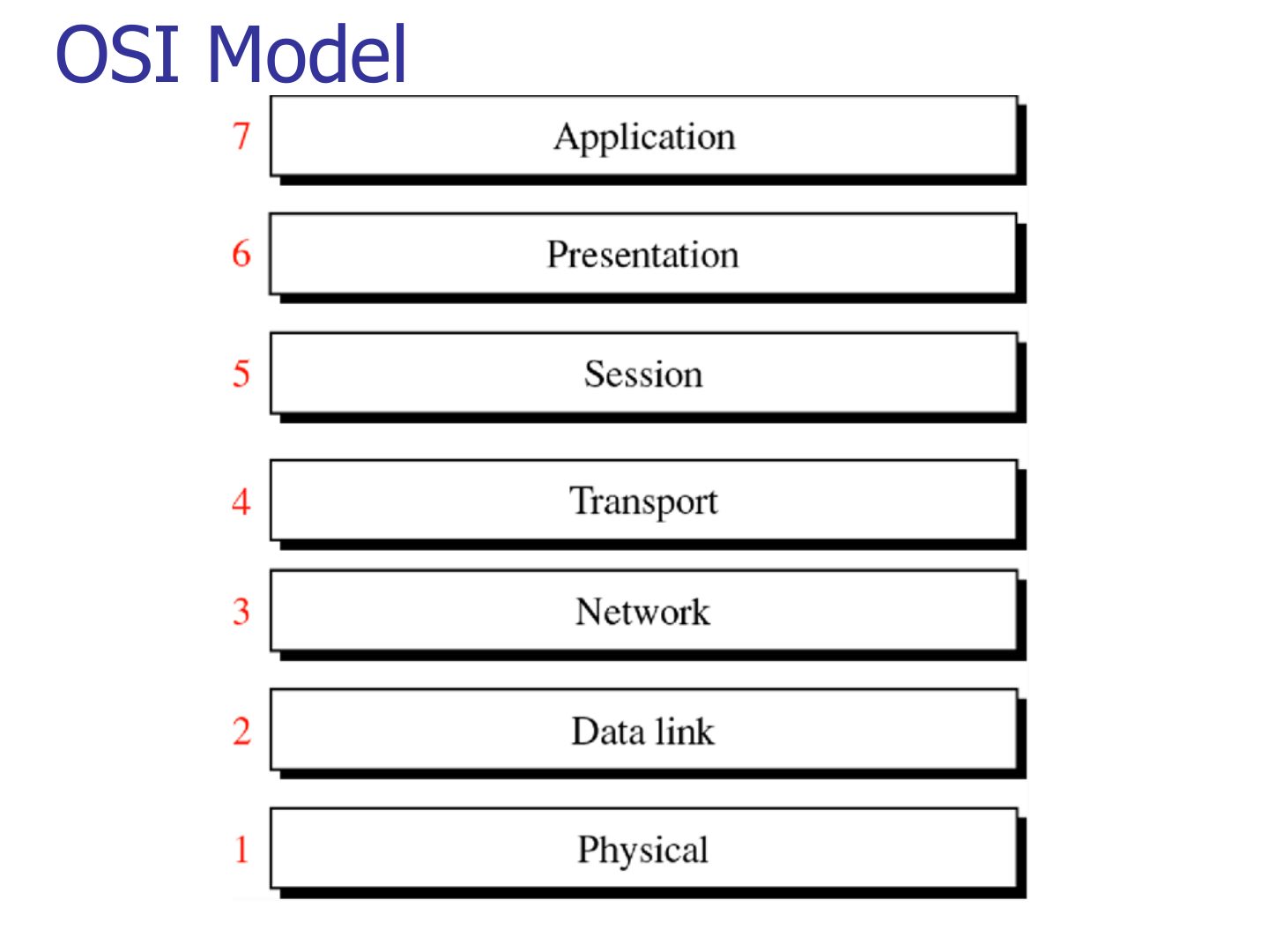
Exam angle
Which OSI layer number is the transport layer?
Which layer sits directly above the network layer in OSI?
OSI Model
Notes
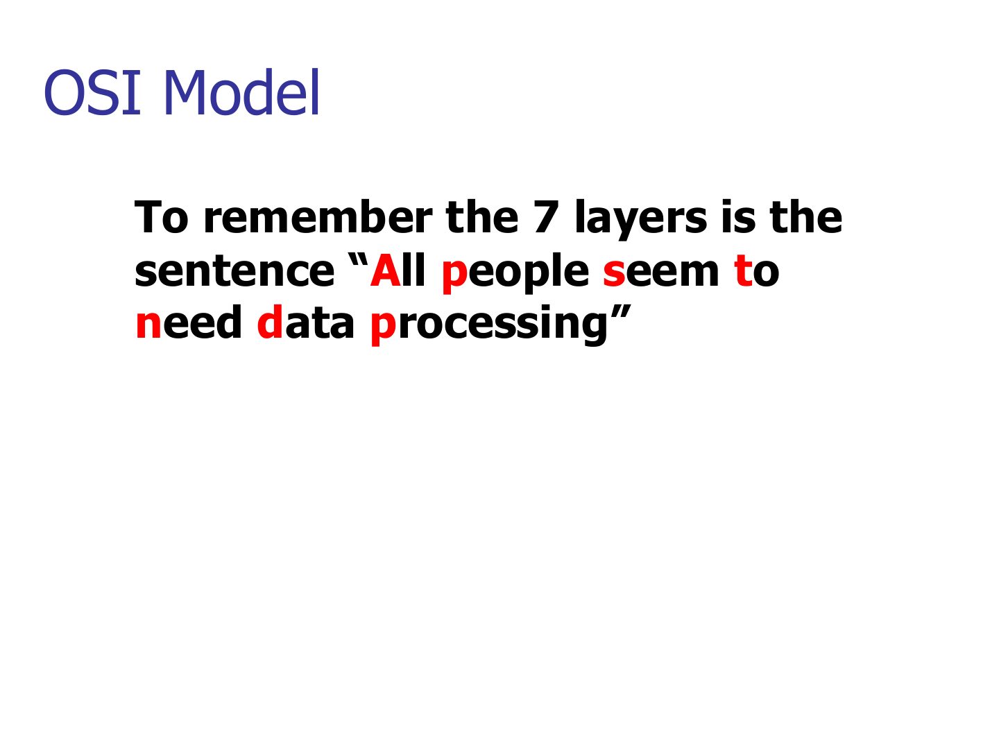
Top-down: All People Seem To Need Data Processing = Application, Presentation, Session, Transport, Network, Data link, Physical.
Memory trick Bottom-up version: “Please Do Not Throw Sausage Pizza Away”.
OSI Protocols Implementation
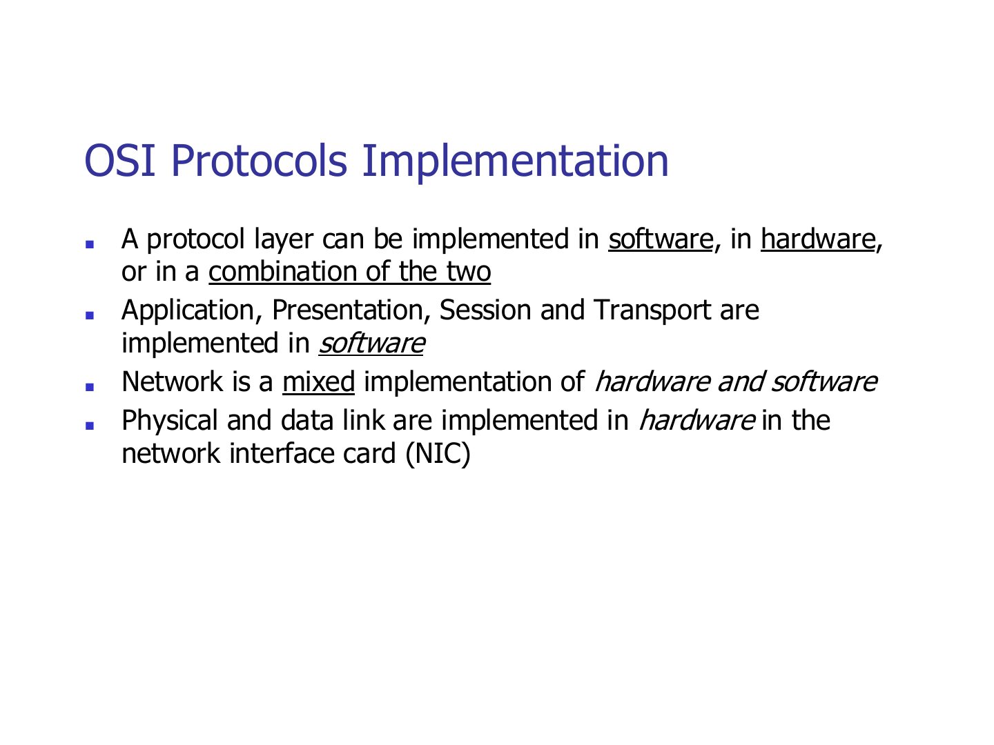
Exam angle
Which layers are implemented in hardware on the NIC?
The network layer is implemented in a mix of hardware and software.
Peer-to-Peer Processes
Notes
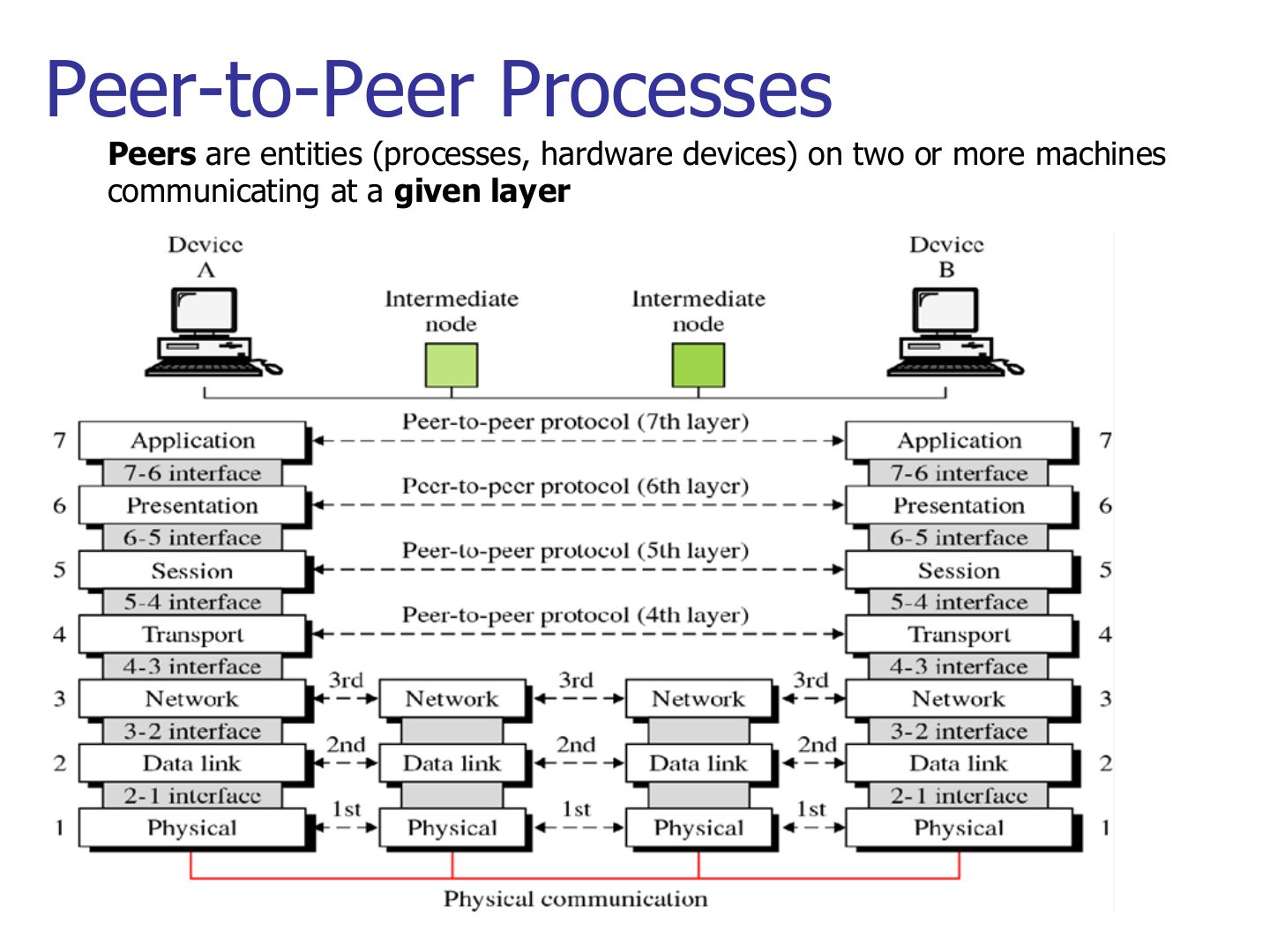
Layers 4–7 talk end to end; layers 1–3 talk hop by hop with every intermediate node.
OSI model-Basic Operation
Notes
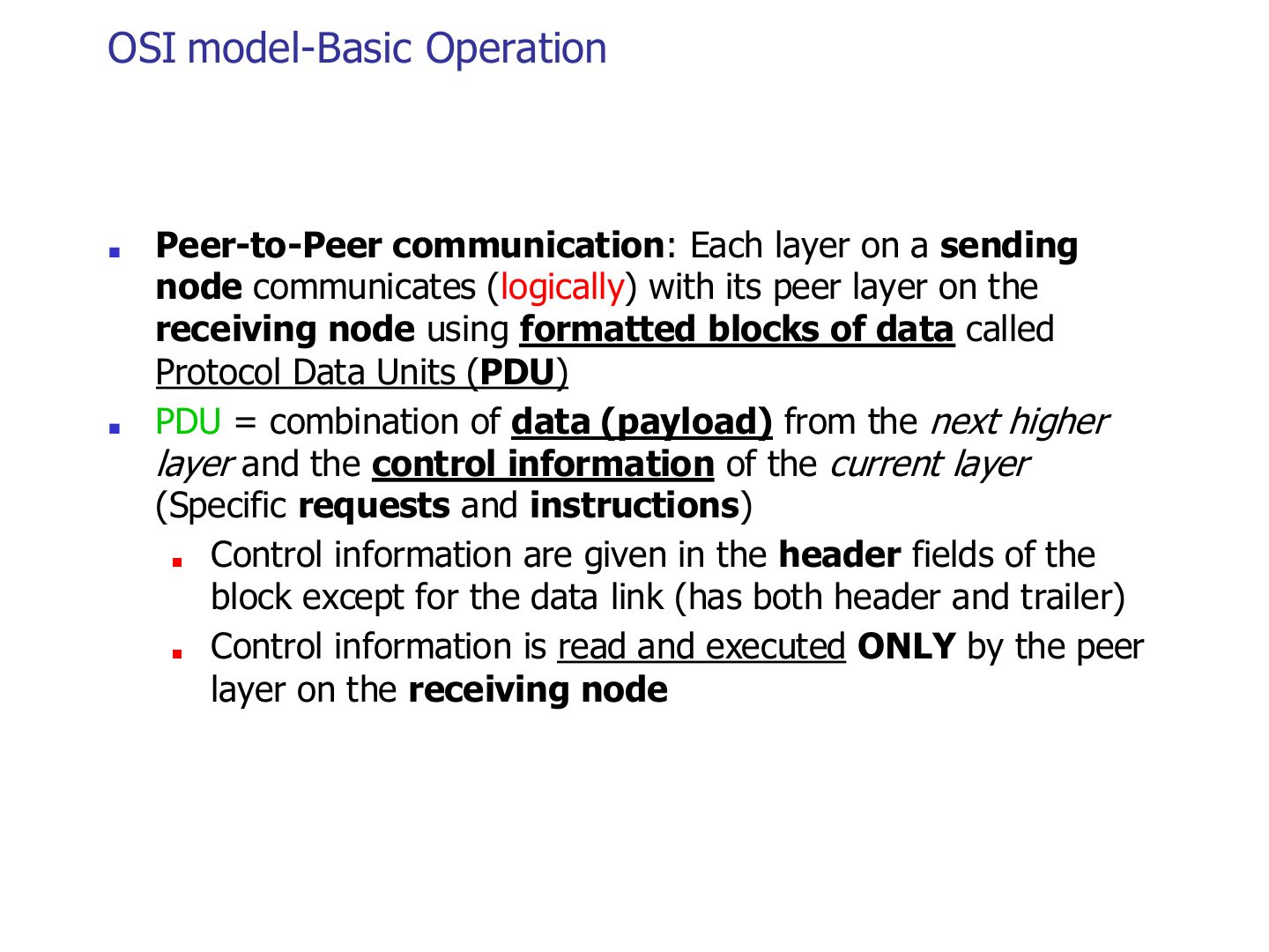
Control info goes in a HEADER. Data link is the exception: it adds a header AND a trailer.
Trap Only the data link layer adds a trailer (for error detection).
Seen again Ch 3 Part 1, slide 4: Framing adds the header and trailer
Exam angle
Which layer adds both a header and a trailer?
The header added by the transport layer is read by the receiver’s transport layer only.
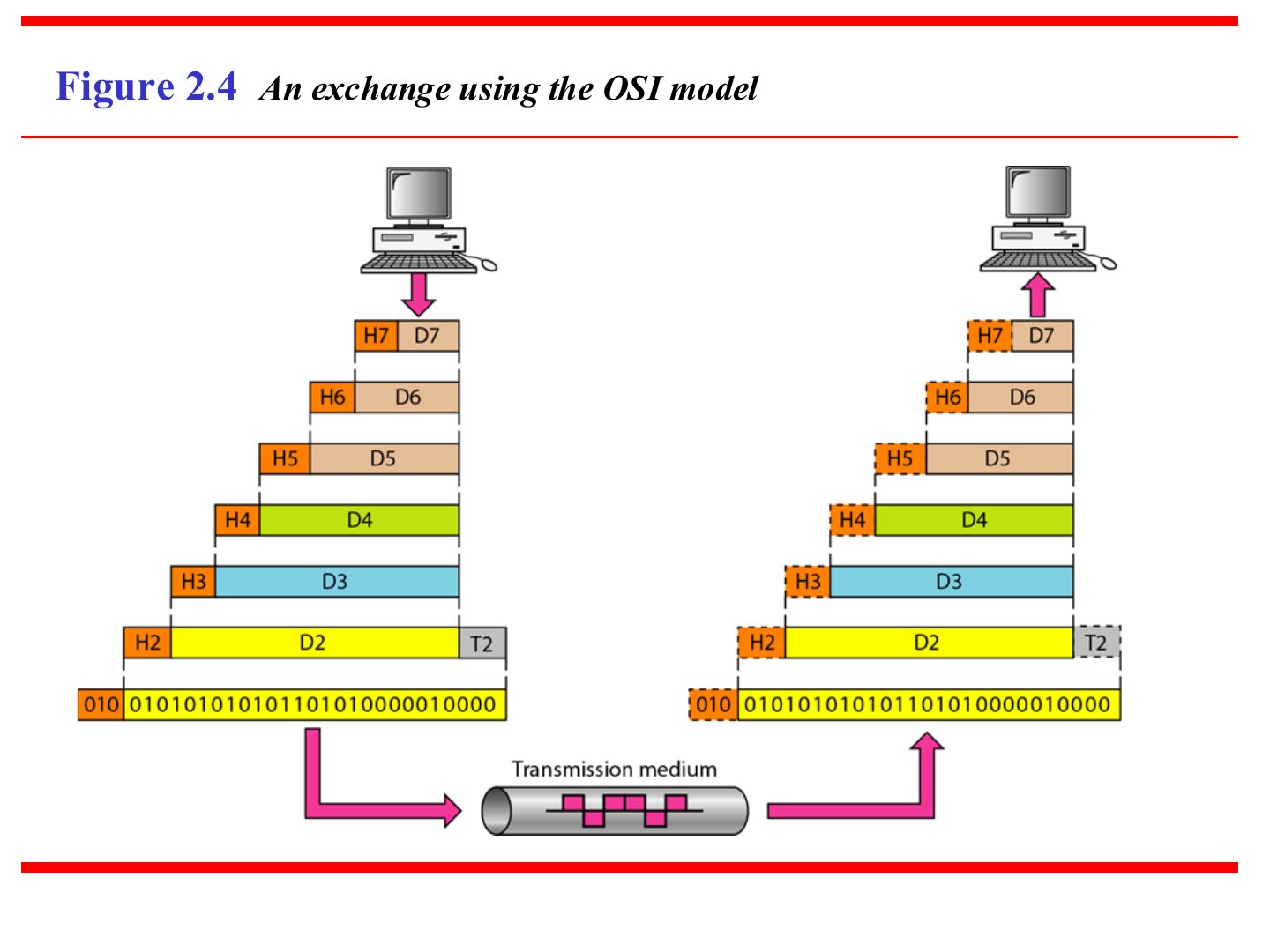
An exchange using the OSI model (Figure 2.4)
Notes
Going down, each layer adds its header (H7 … H2, plus trailer T2). Going up, each layer strips its own.
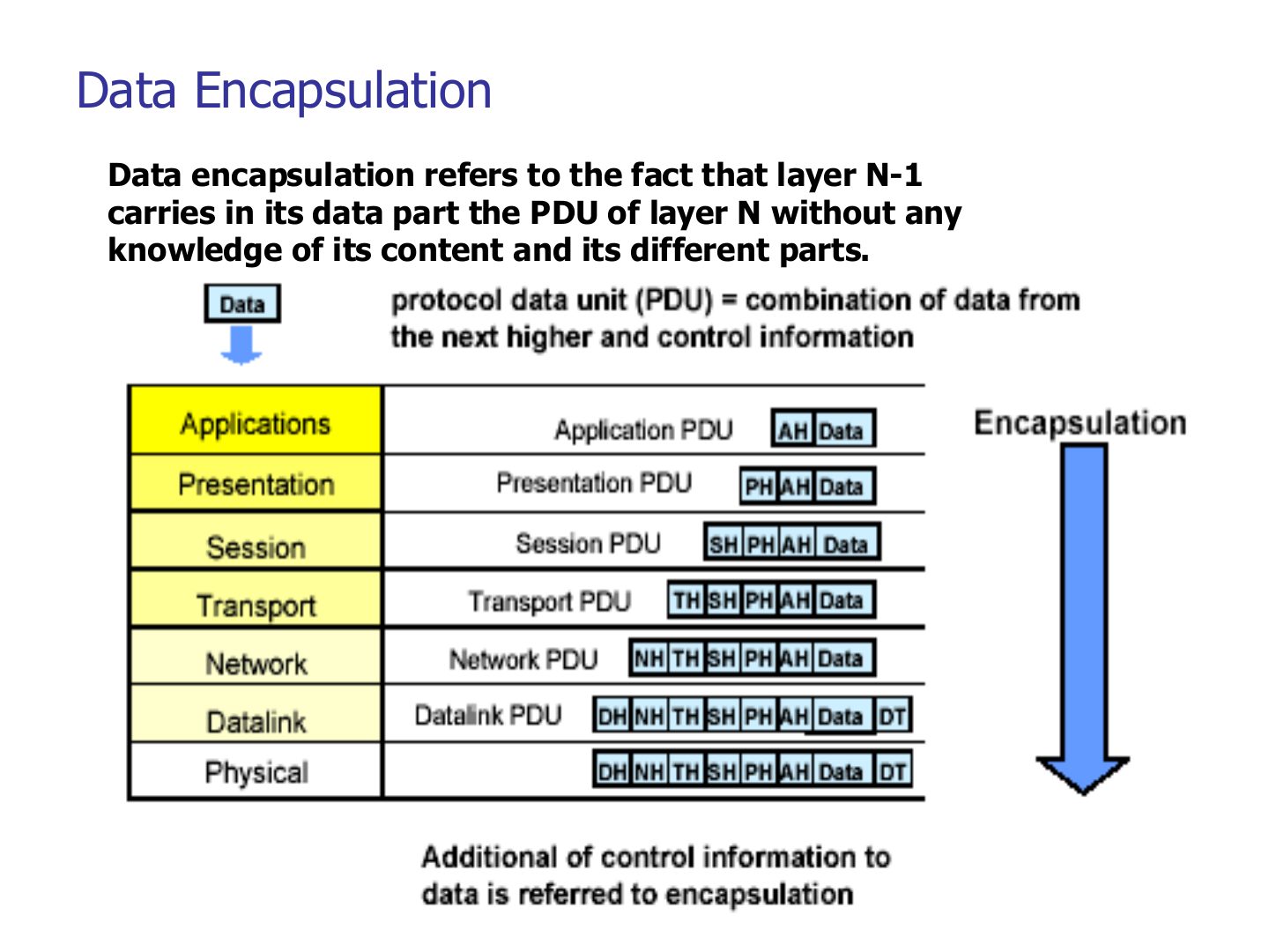
Data Encapsulation
Notes
Encapsulation: layer N-1 carries layer N’s whole PDU as its data, without looking inside.
PDU (N-1) = PDU (N) + control info of N-1.
Exam angle
Data encapsulation means that layer N-1:
During encapsulation, a lower layer inspects and changes the upper layer’s header.
- It carries it untouched.
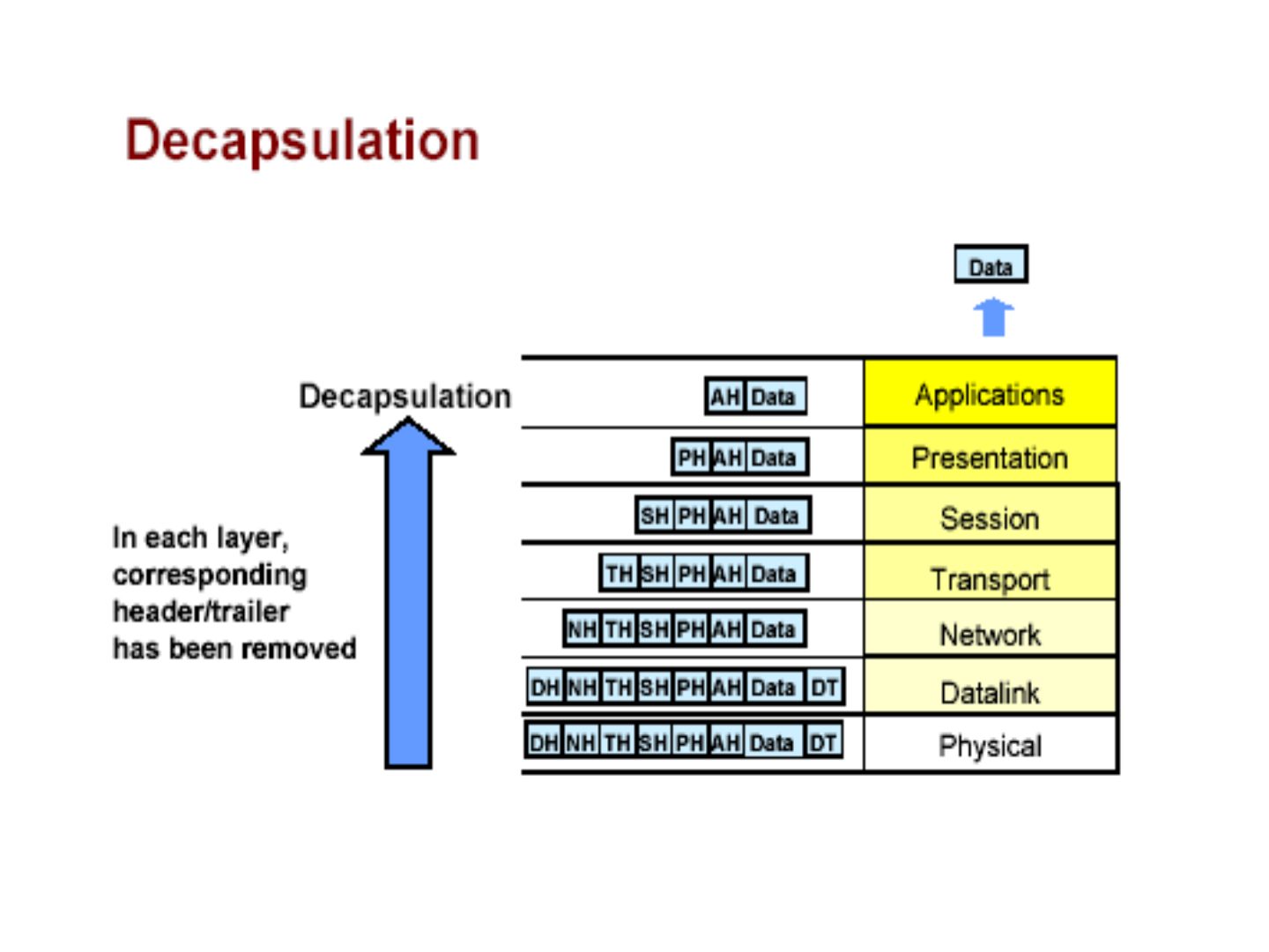
Decapsulation
Notes
Decapsulation = the reverse: each layer removes its own header/trailer and hands the rest up.
How Hosts Talk over a Network
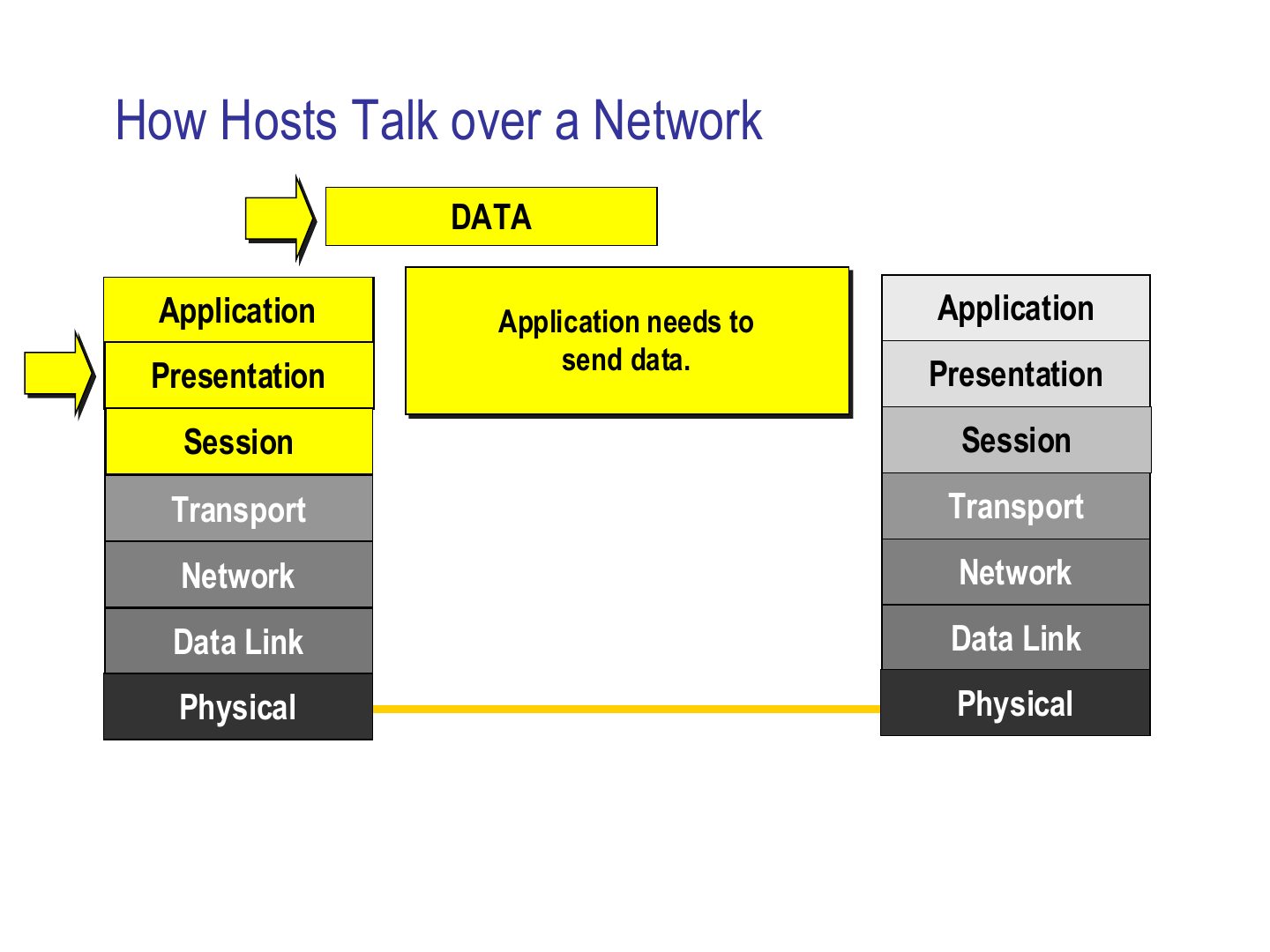
Notes
Slides 17–24 are one animation: follow the yellow arrow down the sender’s stack, across the link, and up the receiver’s stack.
How Hosts Talk over a Network
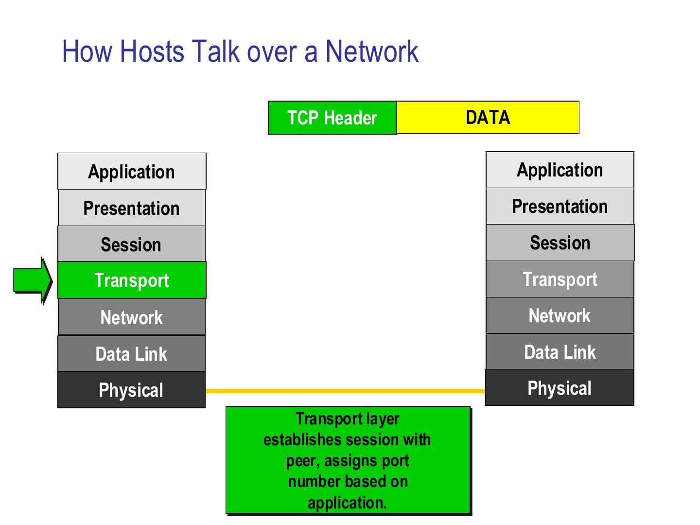
Notes
Seen again Ch 9, slide 9: Process-to-process delivery with ports
How Hosts Talk over a Network
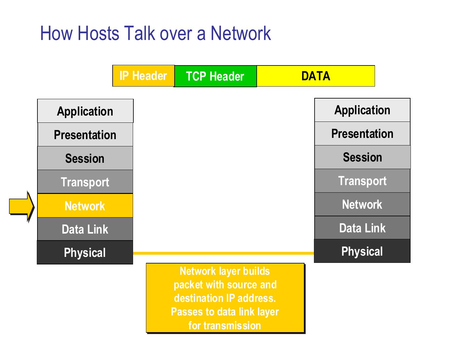
How Hosts Talk over a Network
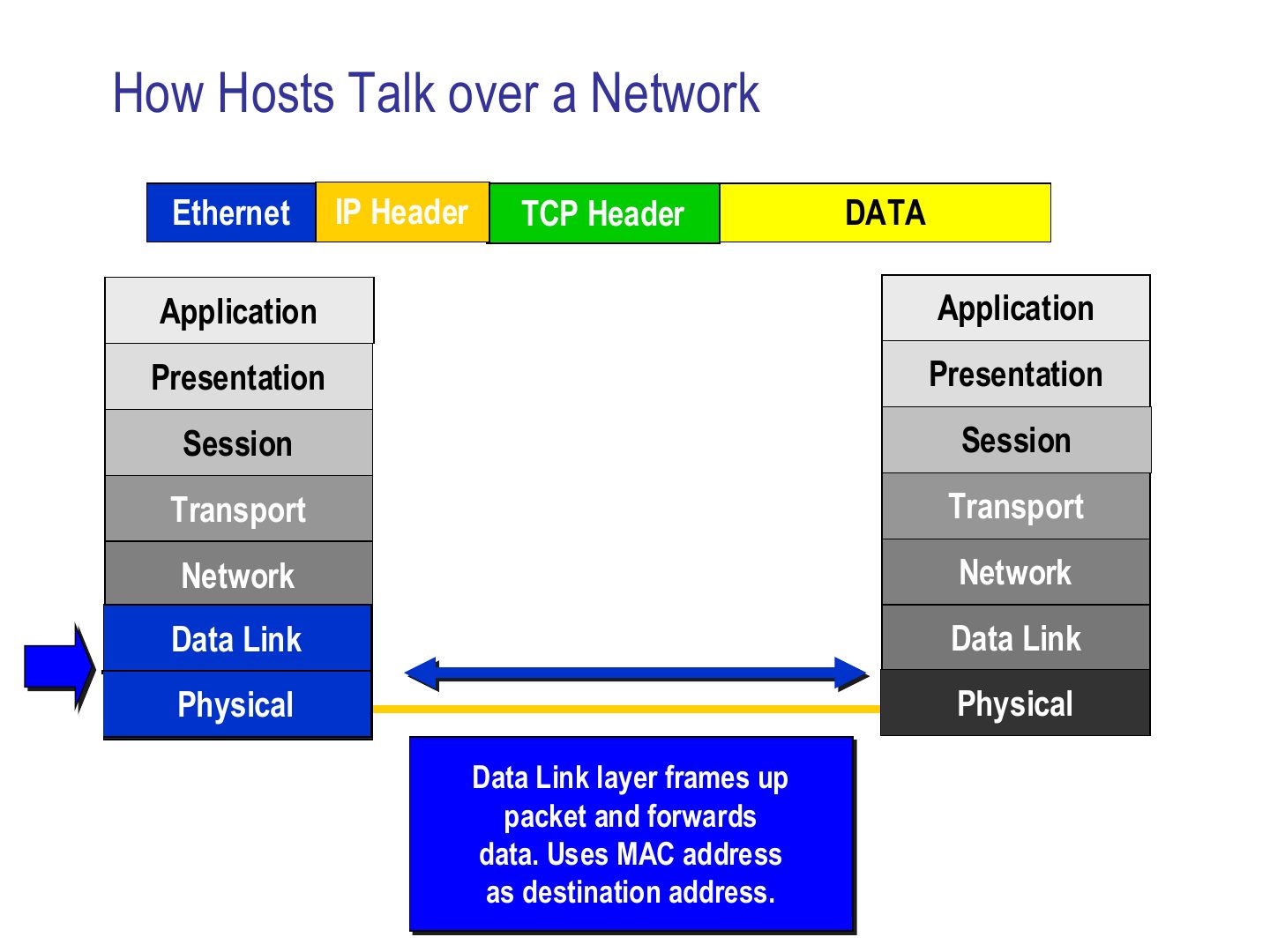
Notes
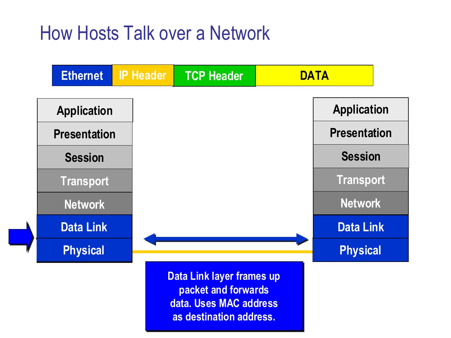
Data link wraps it in a frame (Ethernet header) using the MAC address of the next device. Physical sends bits.
How Hosts Talk over a Network
Notes
Receiver: physical gets bits, data link checks the MAC address and removes the frame header.
How Hosts Talk over a Network
Notes
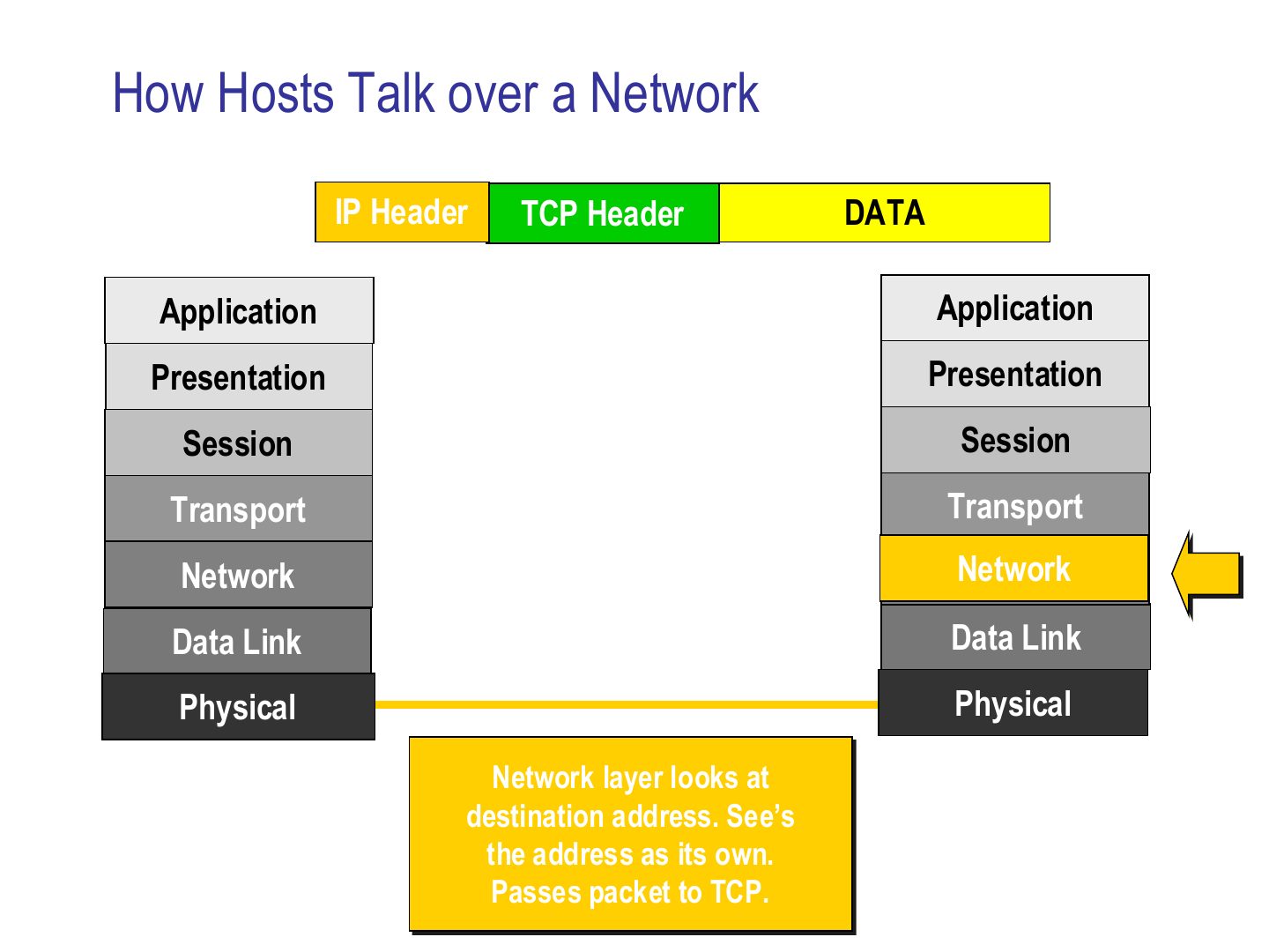
Network sees its own IP as the destination and passes the packet up to TCP.
How Hosts Talk over a Network
Notes
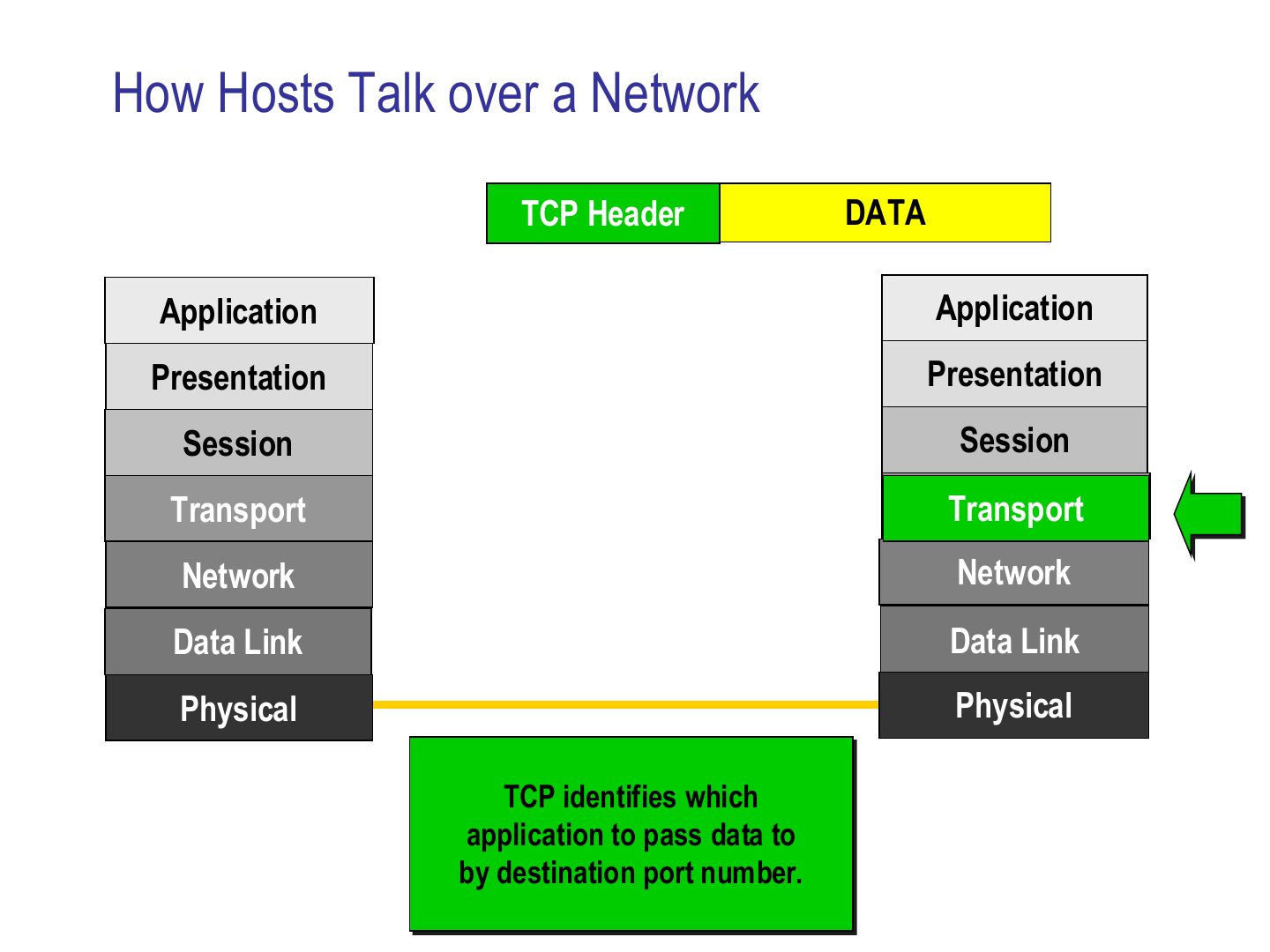
TCP uses the DESTINATION PORT to pick which application gets the data.
How Hosts Talk over a Network
Notes
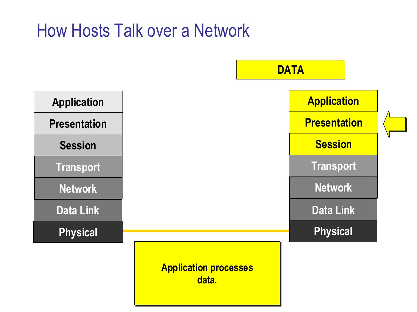
The application finally processes the data. Order of headers on the wire: Ethernet | IP | TCP | data.
Exam angle
On the wire, the order of headers in front of the data is:
Which address does the receiving transport layer use to choose the application?
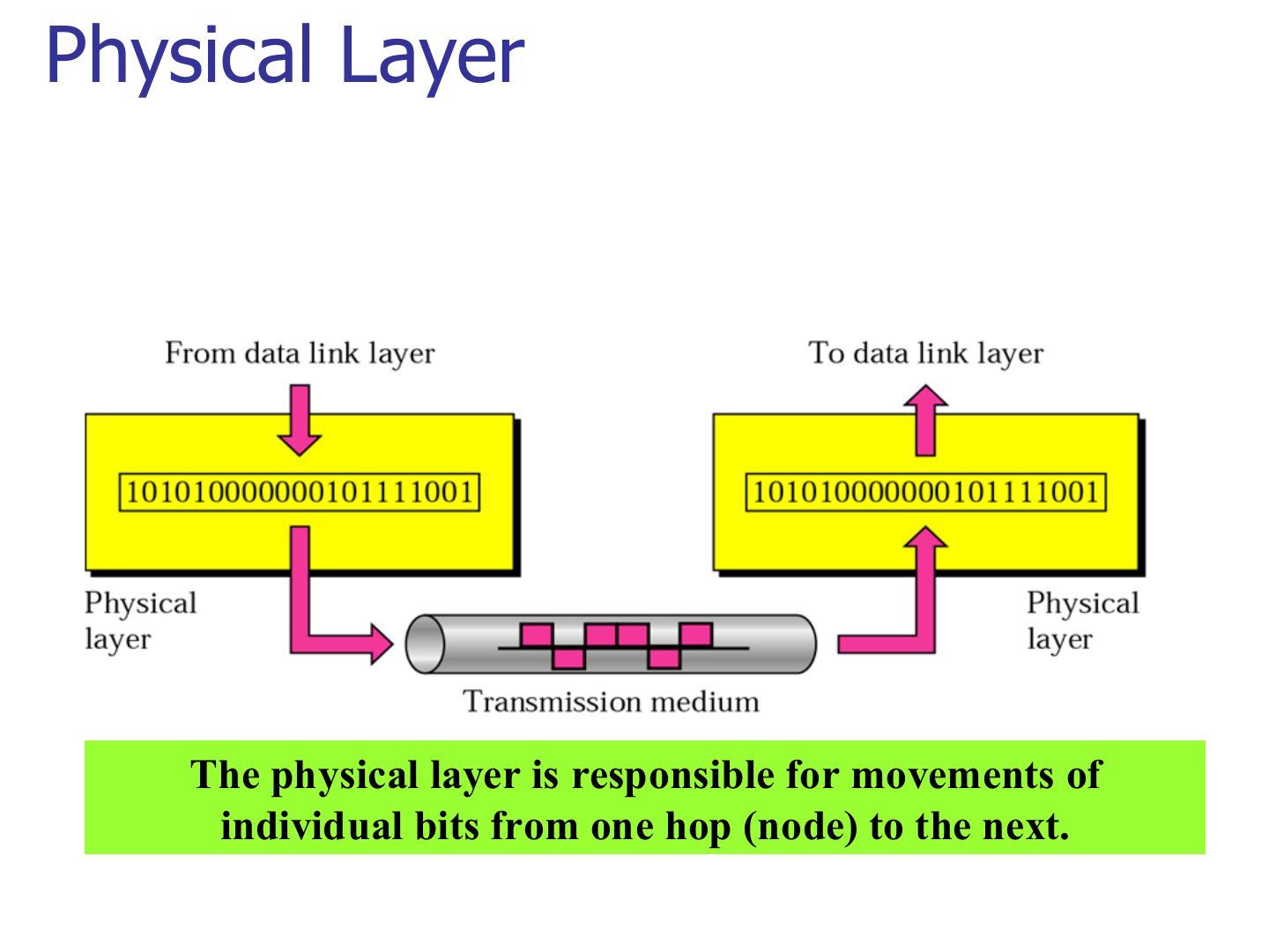
Physical Layer
Exam angle
The physical layer is responsible for moving:
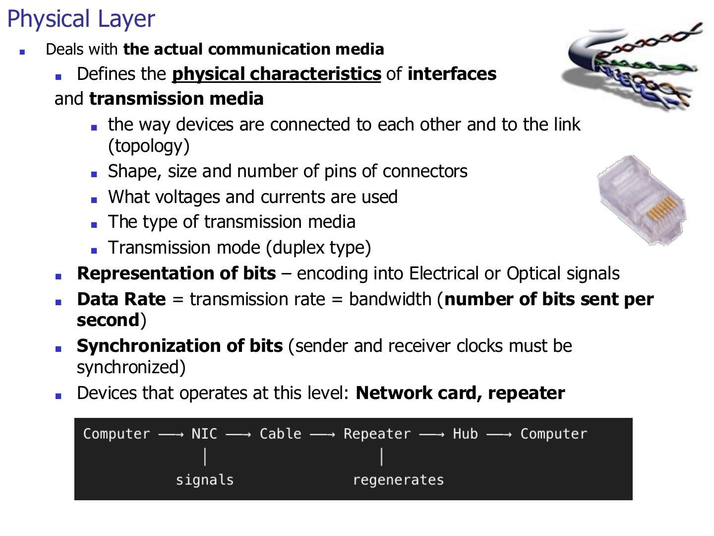
Physical Layer
Notes
Devices at layer 1: NIC (its physical part), repeater, hub.
Seen again Ch 2 Part 1, slide 2: The physical layer in depth
Seen again Ch 6, slide 4: Hubs and repeaters
Exam angle
Which device operates only at the physical layer?
Data rate (bits per second) is defined by the physical layer.
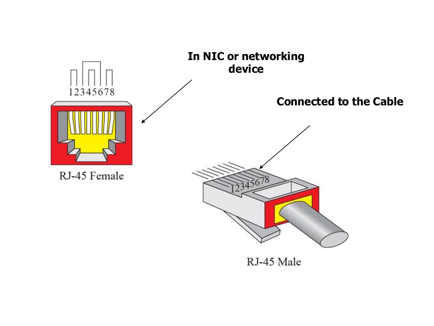
RJ-45 connector
Notes
The connector shape and pins are physical-layer details. RJ-45: female in the NIC, male on the cable.
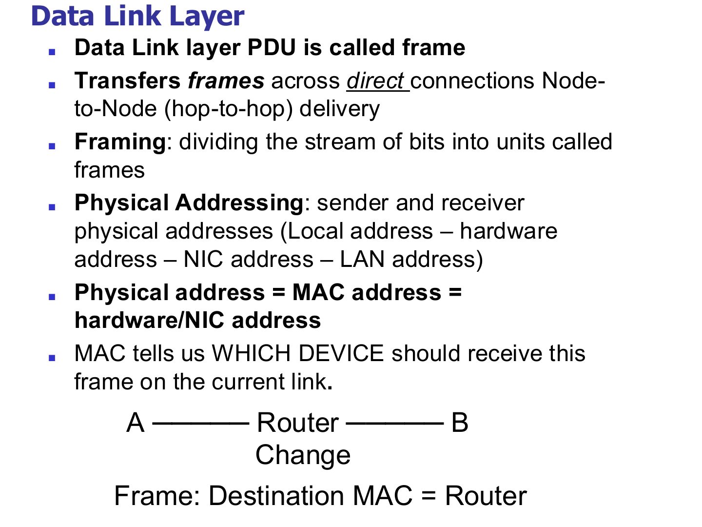
Data Link Layer
Notes
Trap Destination MAC = the NEXT HOP, not the final host. Destination IP = the final host.
Exam angle
The PDU of the data link layer is the:
Host A sends to host B through one router. The destination MAC address in A’s frame is:
Note: data link layer
Data Link Layer
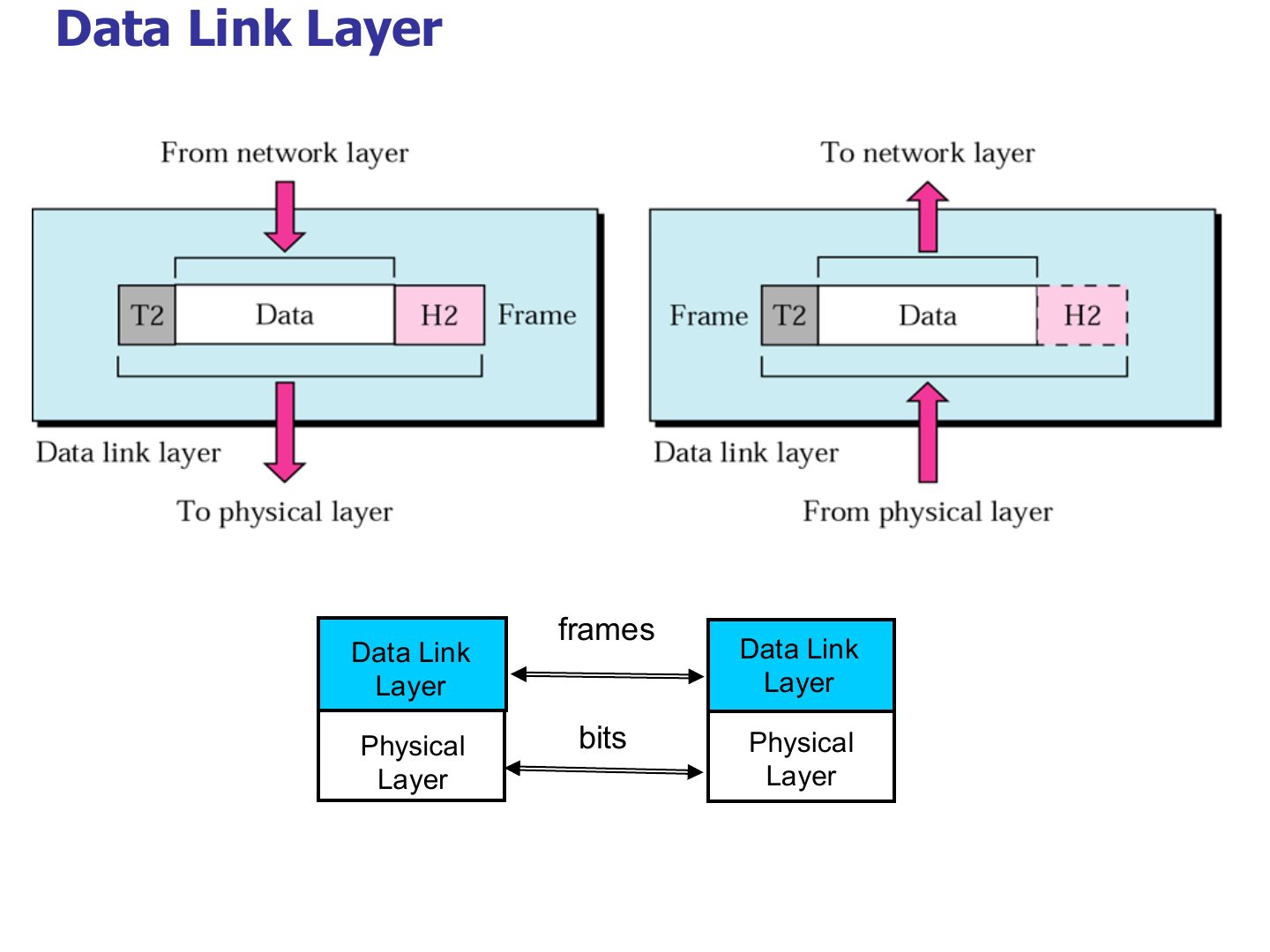
Notes
Header H2 in front AND trailer T2 at the end: the only layer with a trailer.
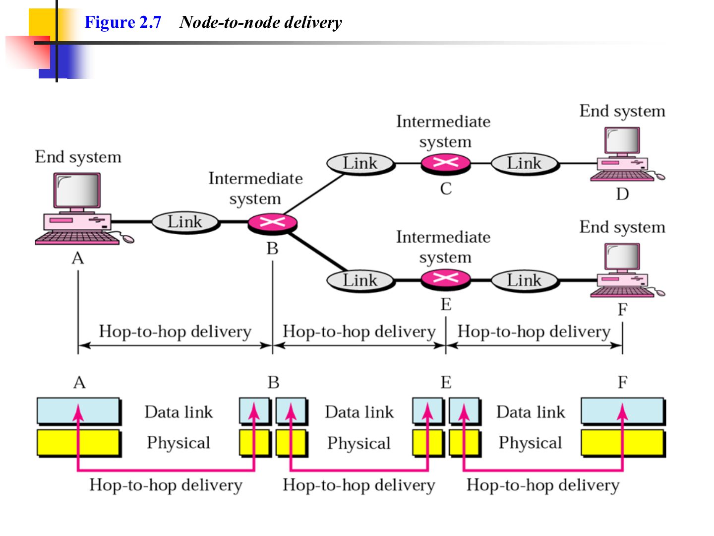
Node-to-node delivery (Figure 2.7)
Example 1 (Figure 2.8)
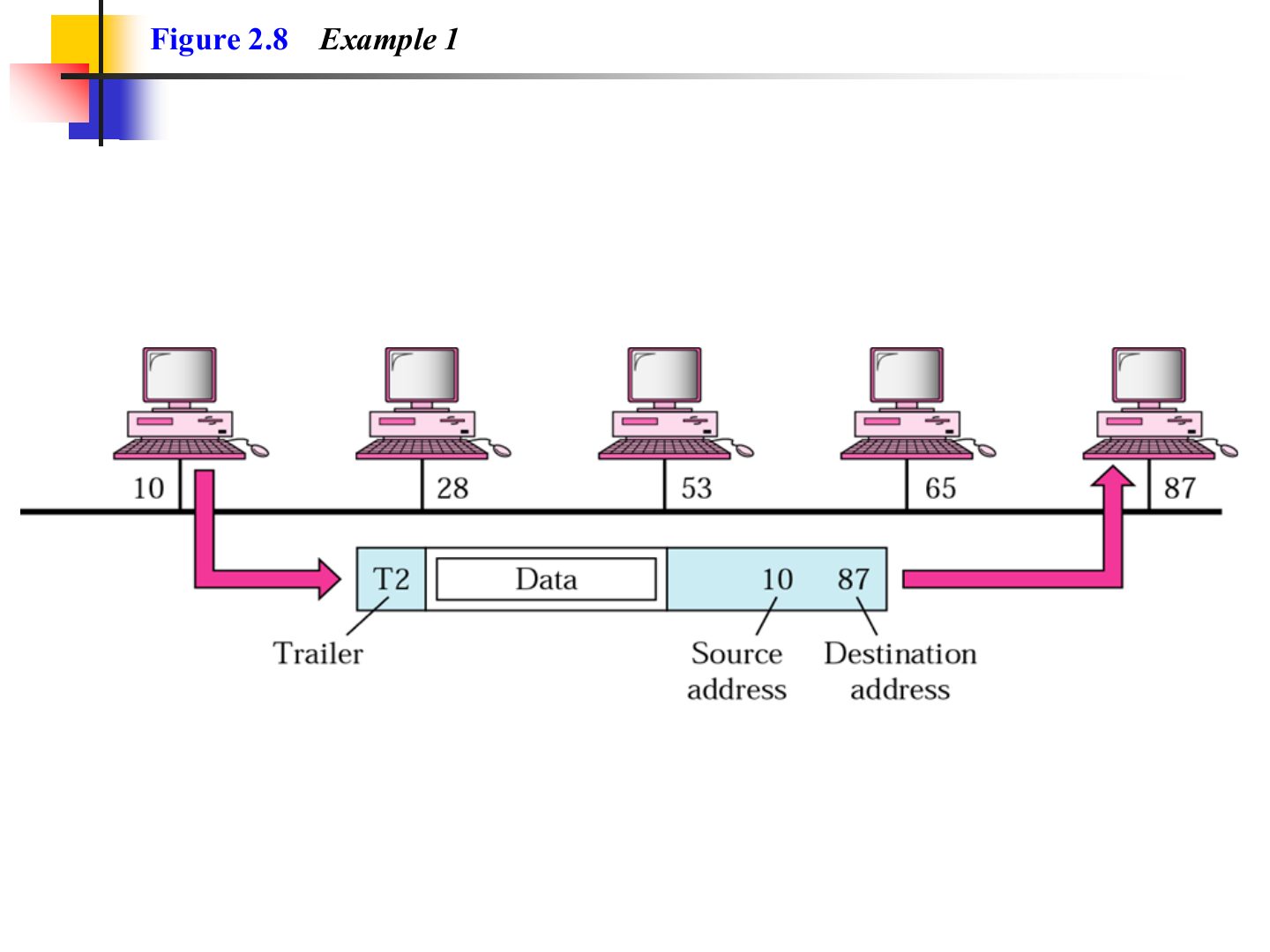
Notes
Same link (a bus), so the frame carries physical addresses 10 → 87 and every station sees it, but only 87 keeps it.
Exam angle
On a bus LAN, station 10 sends a frame to station 87. Which stations receive it and which one keeps it?
Compare with the model answer
All stations on the bus receive the bits, but each compares the destination physical address with its own. Only 87 matches, so only 87 keeps the frame; the rest drop it.
Network Layer
Notes
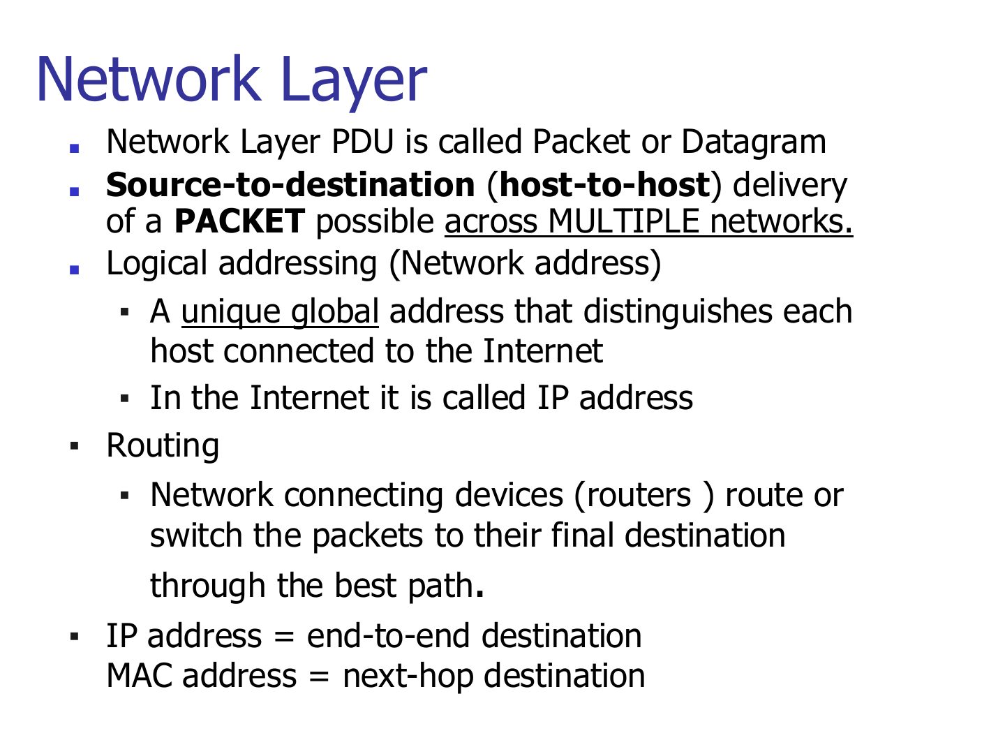
Memory trick IP = end-to-end destination. MAC = next-hop destination.
Seen again Ch 7, slide 3: Network-layer duties in depth
Exam angle
Host-to-host delivery across multiple networks is the job of the:
The IP address changes at each hop, while the MAC address stays the same end to end.
- It’s the opposite: IP stays, MAC changes at each hop.
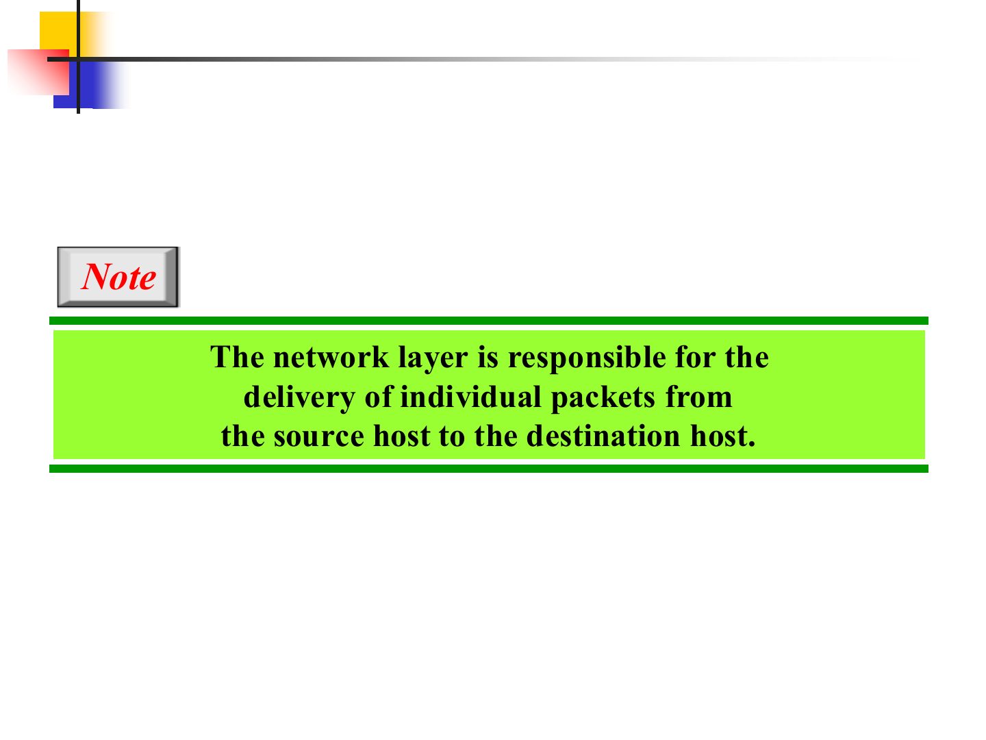
Note: network layer
Network Layer
Notes
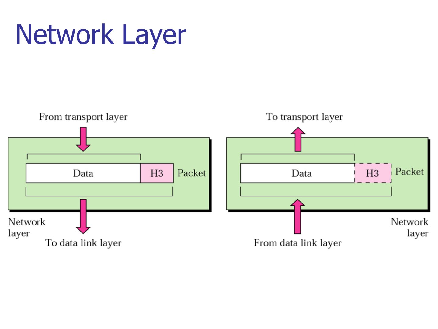
Only a header (H3), no trailer.
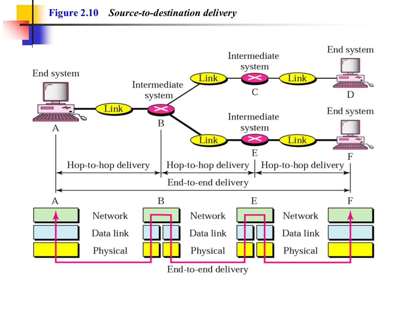
Source-to-destination delivery (Figure 2.10)
Example 2 (Figure 2.11)
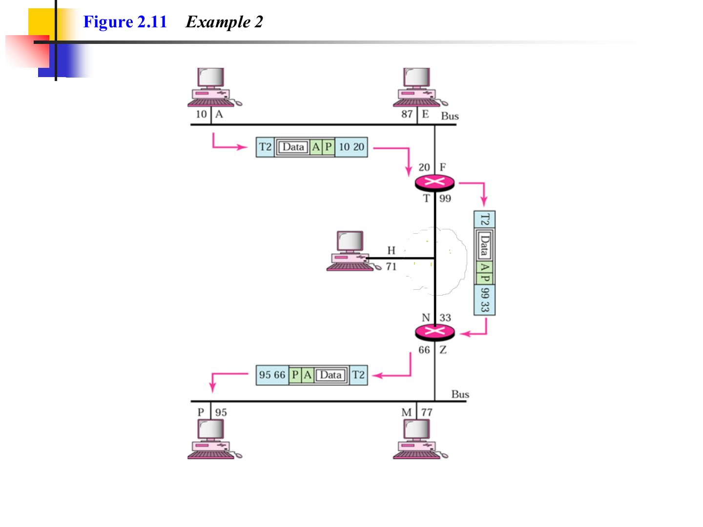
Notes
The logical (IP) addresses A → P stay the same all the way; the physical addresses are rewritten on each link.
Exam angle
A packet travels from host A to host P across two routers. Which addresses change on the way and which stay the same?
Compare with the model answer
The logical (IP) source and destination stay A and P end to end. The physical (MAC) source and destination are replaced on every link, because each frame only travels one hop.
Transport Layer
Notes
The network layer treats every packet independently; transport stitches them back together.
Seen again Ch 9, slide 3: Transport-layer services
Exam angle
Transport-layer addressing uses:
The transport layer PDU is a:
Note: transport layer
Reliable process-to-process delivery of a message (Figure 2.12)
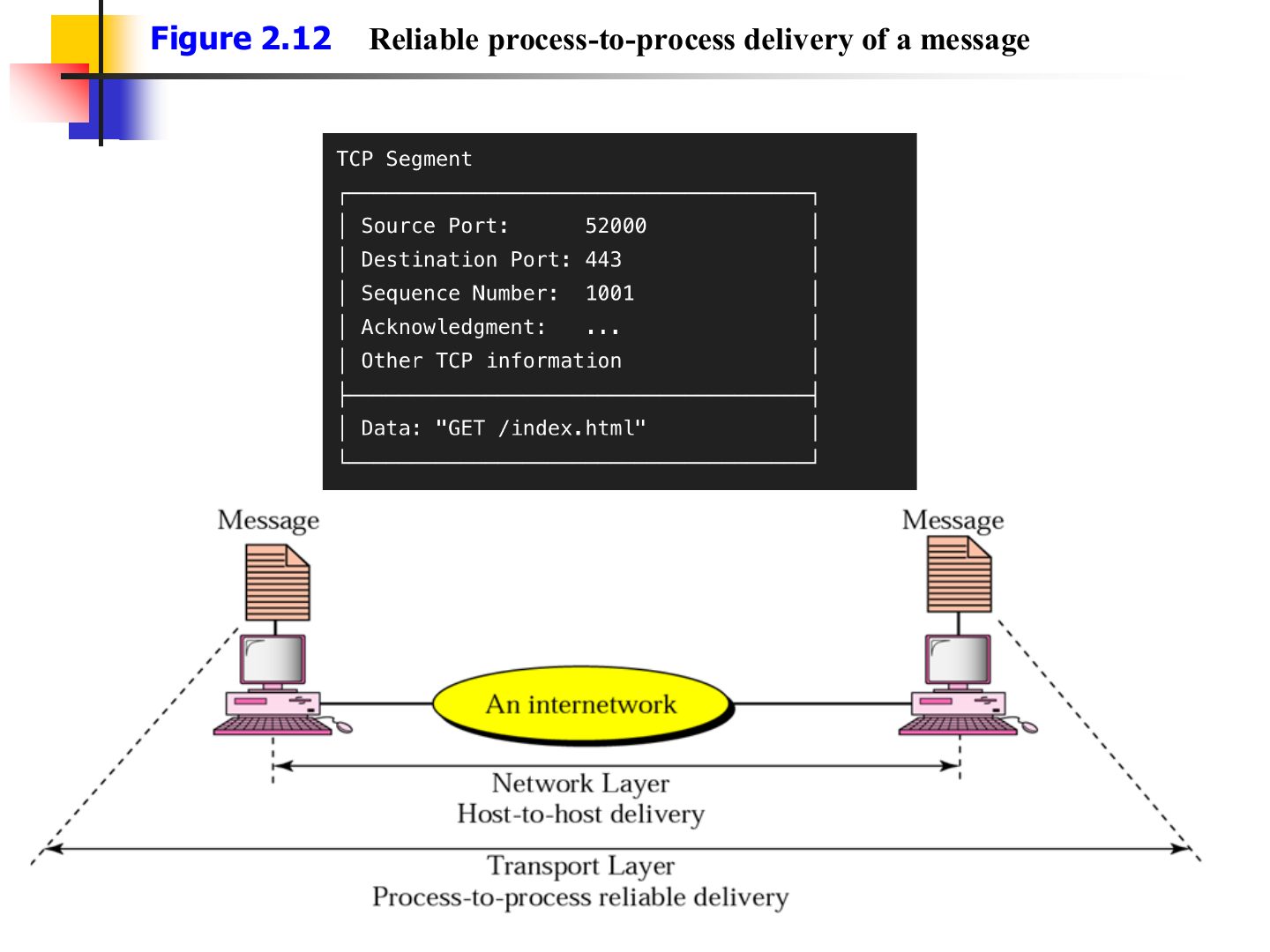
Transport layer (Figure 2.12)
Notes
Transport splits the message into segments (each with H4) and reassembles them at the receiver.
Addressing
Notes
Three addresses in TCP/IP: physical (MAC), IP (logical), port.
Layer Addresses
Notes
Memory trick Bottom-up: MAC (L2) → IP (L3) → Port (L4).
Exam angle
Which address belongs to the data link layer?
Session
Notes
Session: set up, manage and end sessions; keep each application’s data separate.
Synchronization: checkpoints so a long transfer resumes after a crash instead of restarting.
Exam angle
Adding checkpoints so a long transfer can resume after a crash is done by the:
Session layer (Figure 2.12)
Notes
The “syn” marks are the synchronization checkpoints.
Presentation
Notes
Memory trick Presentation is about HOW data looks: translate, encrypt, compress.
Exam angle
Encryption, compression and translation belong to the:
Presentation layer (Figure 2.13)
Application
Notes
Application layer = the services users see: web (HTTP), remote login (Telnet), file transfer (FTP), mail.
Seen again Ch 10, slide 3: Application layer: DNS
Application layer (Figure 2.15)
TCP/IP Protocol Suite
Notes
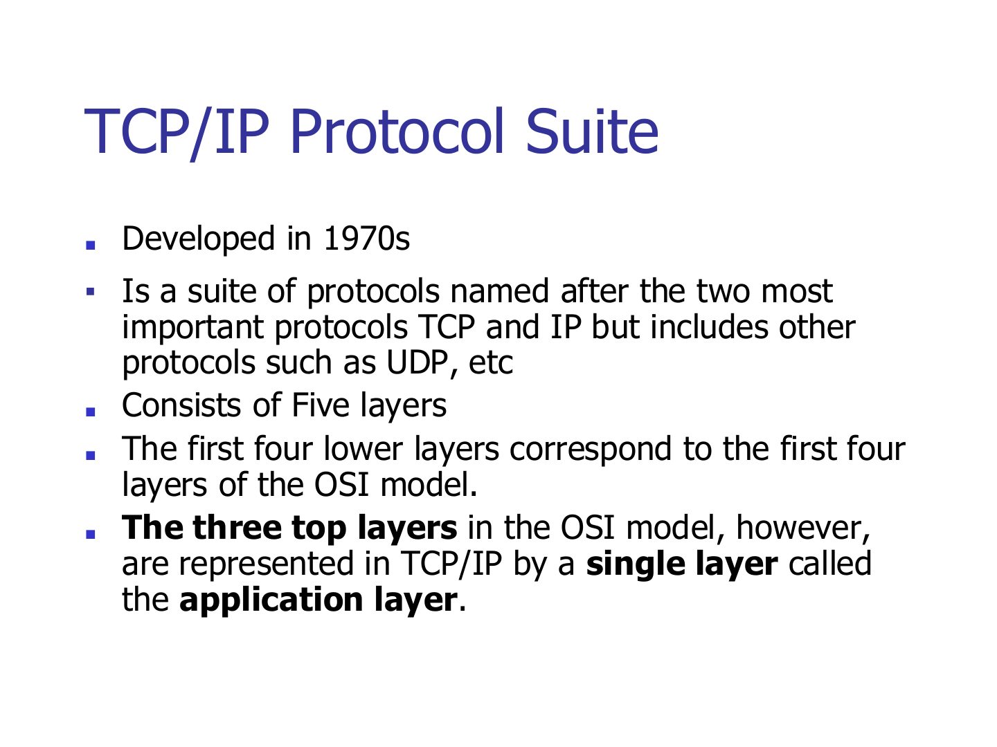
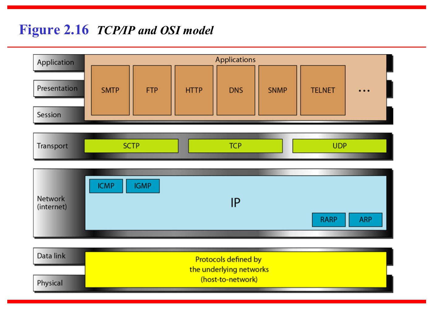
TCP/IP: 5 layers. The bottom 4 match OSI’s bottom 4; OSI’s top 3 (session, presentation, application) are ONE application layer.
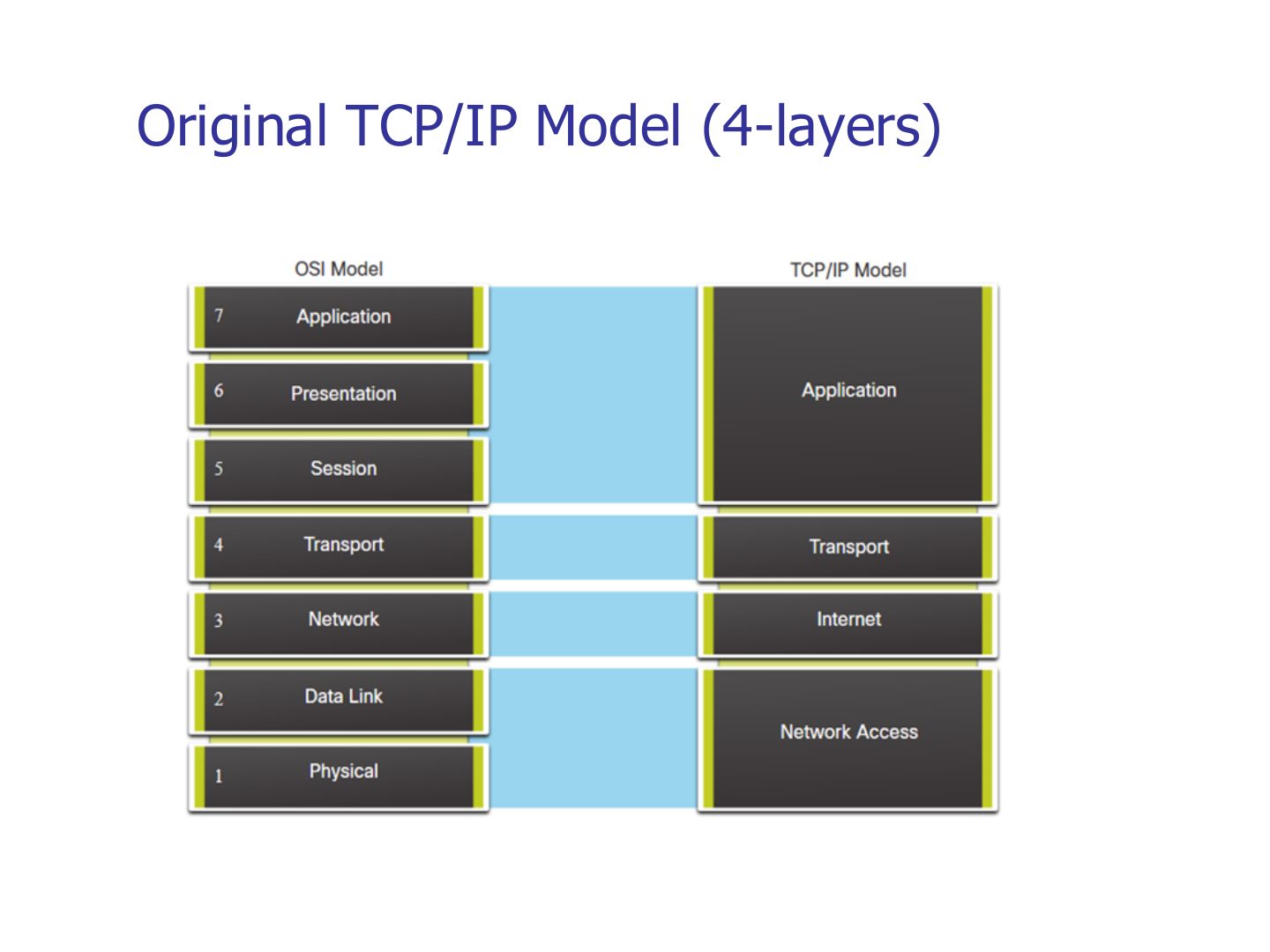
Trap The textbook TCP/IP model has 5 layers; the original TCP/IP model (slide 54) has 4.
Exam angle
In TCP/IP, which OSI layers are merged into the application layer?
The TCP/IP protocol suite in the textbook has five layers.
Layers in the TCP/IP protocol suite (Figure 1.17)
Notes
Memory trick “My Silly Pet Fish Bites”: Message, Segment, Packet, Frame, Bits.
Exam angle
The PDU at layer 3 is called a:
Match: which PDU belongs to the transport layer?
TCP/IP and OSI model
Notes
Same picture as slide 50, drawn side by side.
TCP/IP and OSI model: protocols
Notes
Application: SMTP, FTP, HTTP, DNS, SNMP, Telnet. Transport: TCP, UDP, SCTP. Network: IP + ICMP, IGMP, ARP, RARP.
Exam angle
Which protocol belongs to the transport layer?
ARP and ICMP sit in which TCP/IP layer?
Original TCP/IP Model (4-layers)
Notes
Original TCP/IP: application, transport, internet, network access (= data link + physical).