A link-layer switch operates in which layers?
Connecting Devices and Virtual LANs
Hubs, link-layer switches and routers: which layer each works at, how a switch learns and filters, why loops cause broadcast storms and how spanning tree fixes them, collision vs. broadcast domains, store-and-forward vs. cut-through, and VLANs. Counting collision and broadcast domains in a drawing is the classic question here, so the notes show how to count.
How to read this page
Every original slide is shown unchanged. Yellow marks on a slide point to a numbered note: hover or tap a mark to jump to its note, and hover a note to see its marks. Questions tagged Past exam appeared on a real paper; Prediction questions are likely angles, not confirmed. Pick an answer to each question: a wrong pick tells you why it is wrong, so you can try again.
All 34 slides
- 1 Connecting Devices and Virtual LANs
- 2 6-1 CONNECTING DEVICES
- 3 Three categories of connecting devices (Figure 6.1)
- 4 Hubs
- 5 A hub
- 6 Hubs
- 7 Interconnecting with hubs
- 8 Link-Layer Switches
- 9 Switches
- 10 Switches vs. hubs
- 11 Link-layer switch
- 12 Switch learning process
- 13 Learning switch (Figure 6.4)
- 14 Loop problem in a learning switch
- 15 Loop problem in a learning switch
- 16 Loop problem in a learning switch: broadcast storm
- 17 Spanning tree: blocking ports
- 18 A system of connected LANs and its graph (Part a) (Figure 6.6)
- 19 Finding the shortest path and the spanning tree for a switch. (Figure 6.7)
- 20 Forwarding and blocking ports after using spanning tree algorithm (Figure 6.8)
- 21 Some switch features
- 22 Isolated collision domains
- 23 Collision domains in a nonswitched and switched network
- 24 Collision domains in a switched network
- 25 Some switch features – cont’d
- 26 Routers
- 27 Routing example
- 28 Typical Organization LAN
- 29 Comparison between switch and router
- 30 Virtual LANs
- 31 A switch using VLAN software
- 32 Two switches in a backbone using VLAN software (Figure 6.12)
- 33 Note: VLANs create broadcast domains
- 34 Advantages Of VLAN
Connecting Devices and Virtual LANs
Notes
Hub (layer 1) → switch (layer 2) → router (layer 3), then loops and spanning tree, then VLANs.
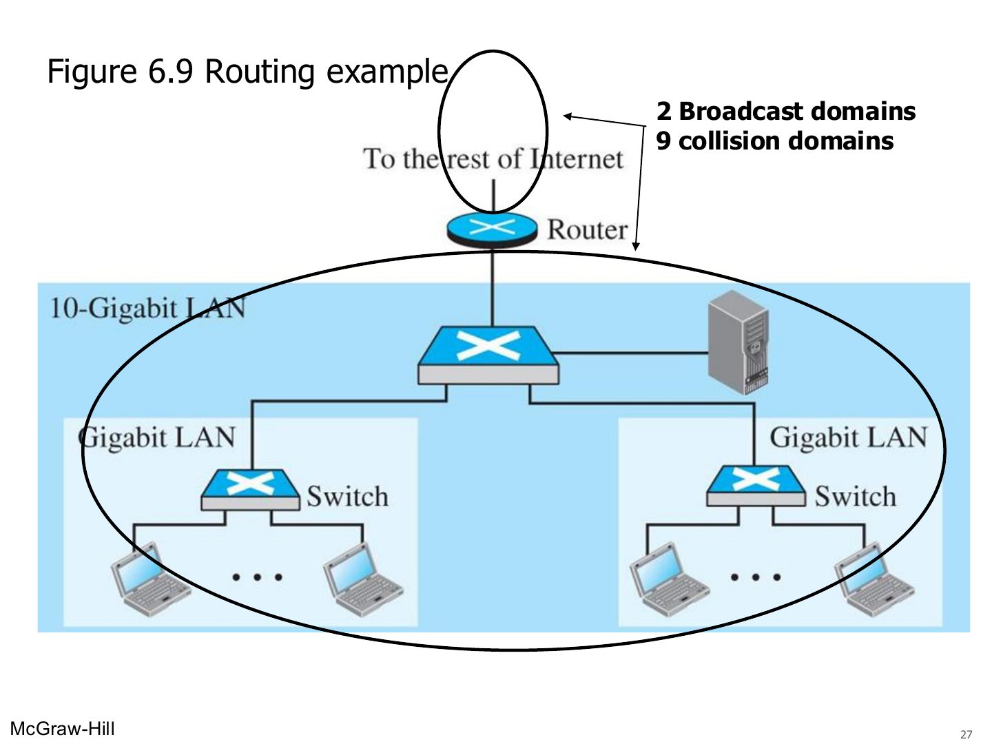
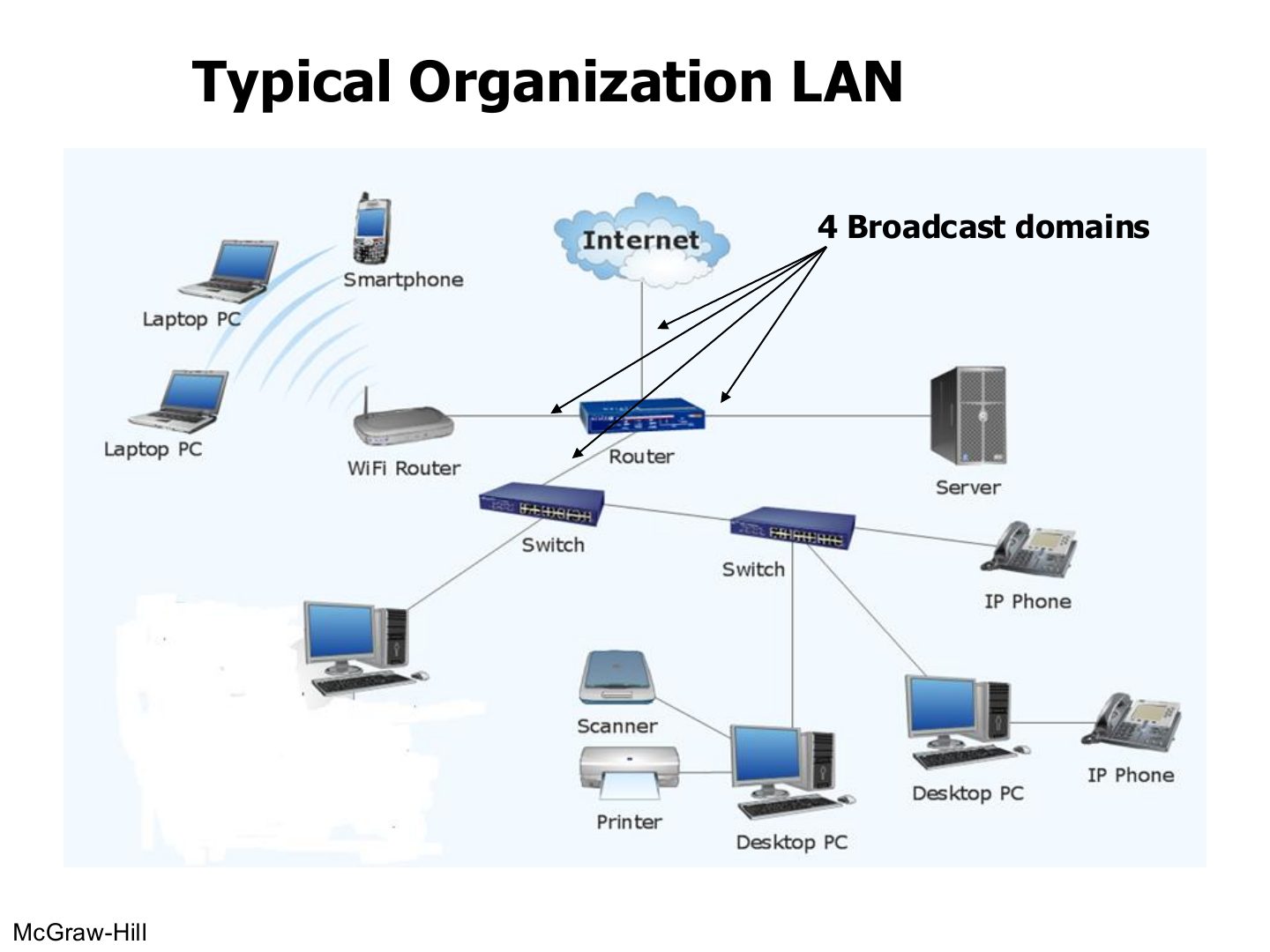
Tip Counting domains: every switch or router PORT starts a new collision domain (a hub port does not). Every router PORT starts a new broadcast domain (switches and hubs do not, unless VLANs are used).
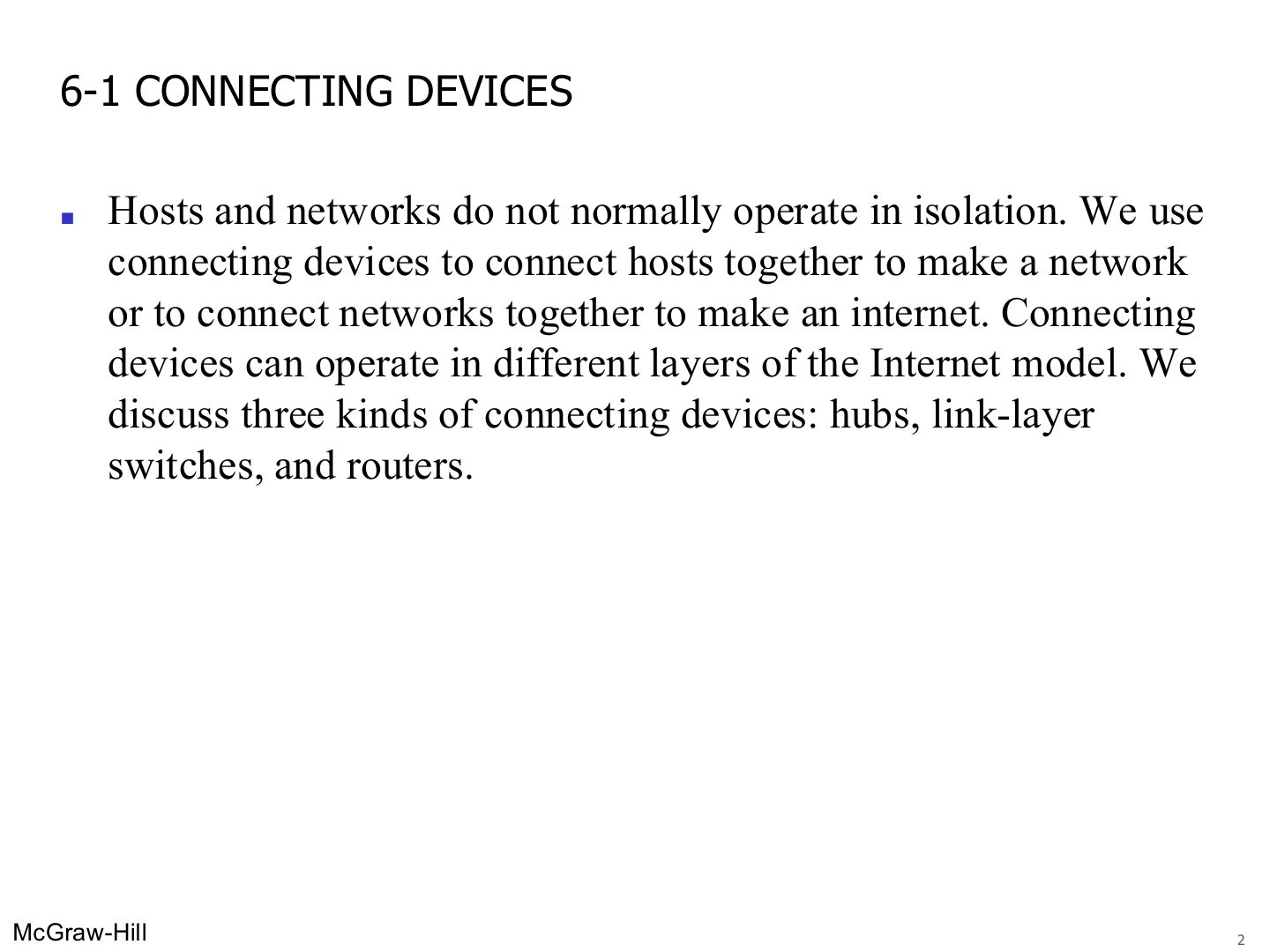
6-1 CONNECTING DEVICES
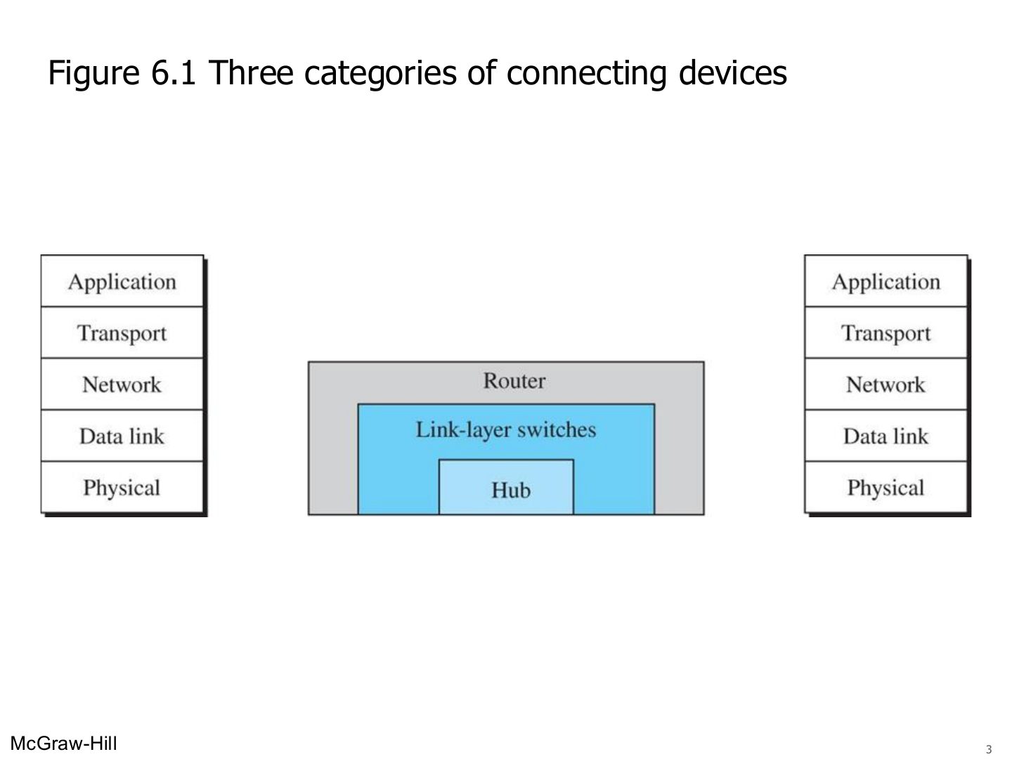
Three categories of connecting devices (Figure 6.1)
Notes
Hub = layer 1 · link-layer switch = layers 1–2 · router = layers 1–3.
Seen again Ch 1 Part 2, slide 5: Devices that don’t use all layers
Exam angle
Which device works at the network layer?
Hubs
Notes
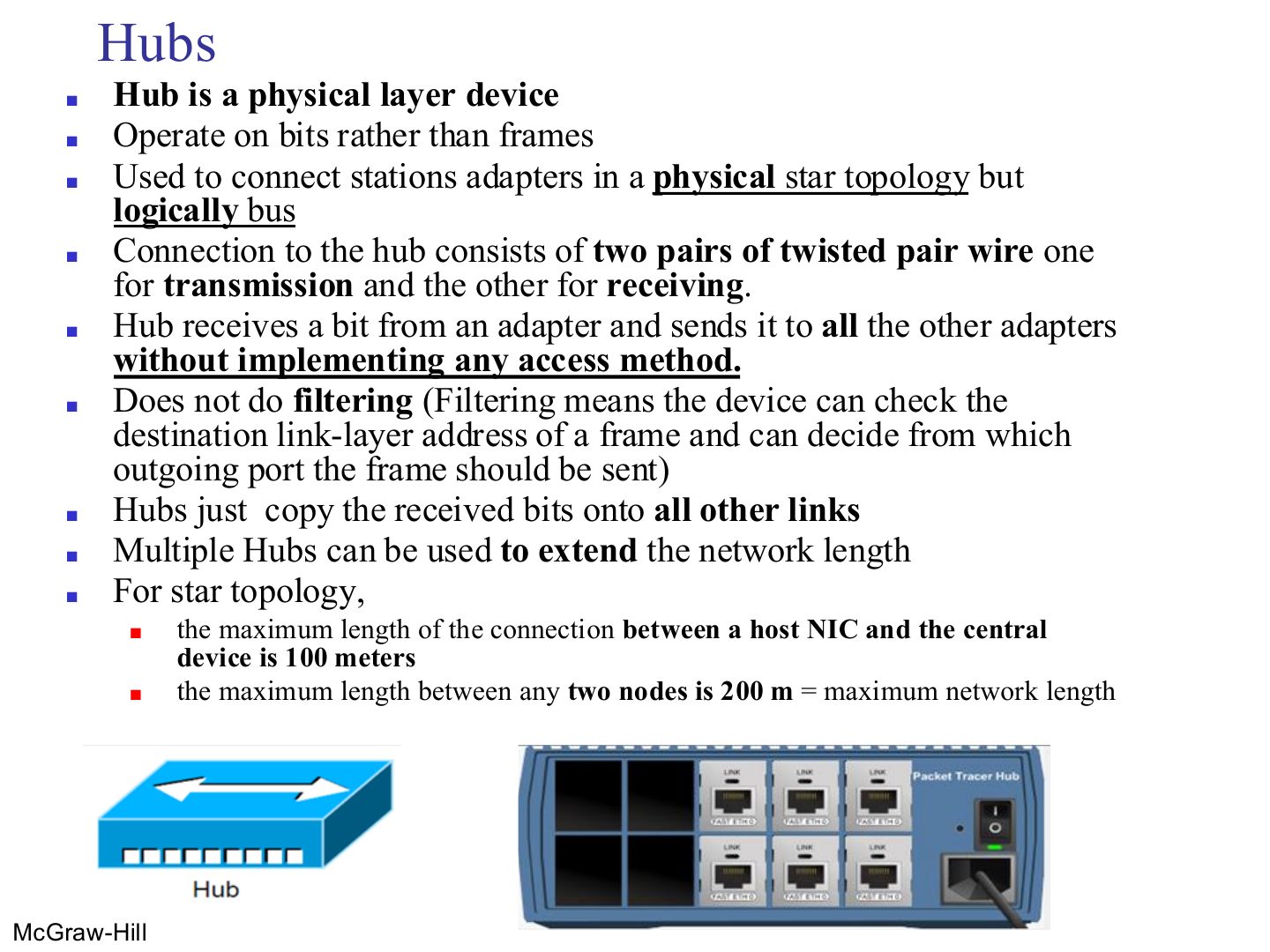
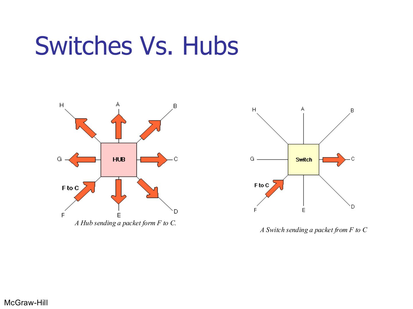
Hub = layer 1: works on BITS, copies every bit to every other port, no filtering, no access method.
Cable host ↔ hub max 100 m, so two hosts can be at most 200 m apart.
Trap A hub does not read MAC addresses at all; it only repeats bits.
Seen again Ch 1 Part 2, slide 26: Physical-layer devices
Exam angle
A hub forwards a received bit to:
Topology of hosts connected to a hub:
A hub performs filtering using MAC addresses.
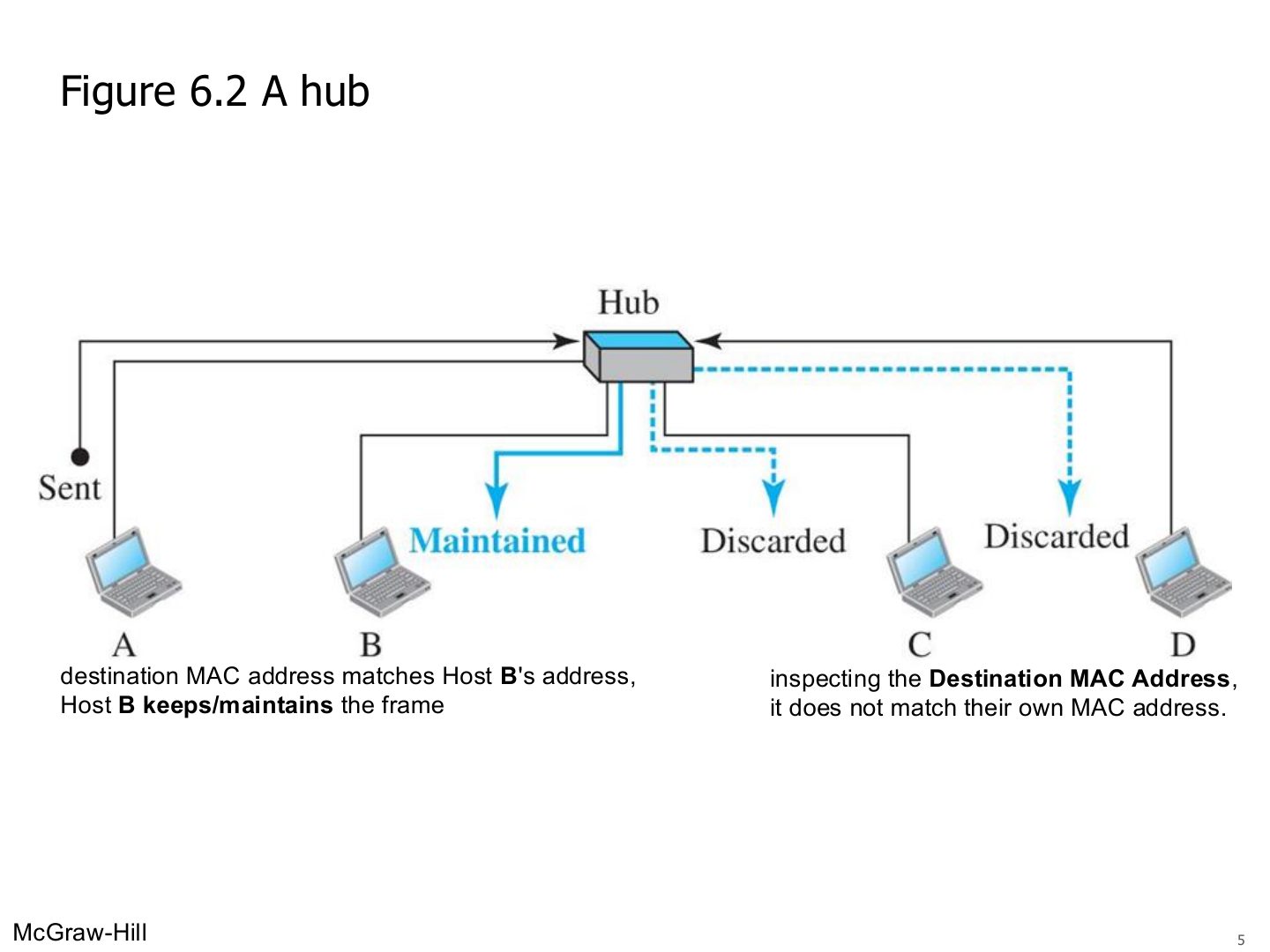
A hub
Notes
Everyone gets the frame. Each NIC checks the destination MAC: B keeps it, C and D discard it.
Hubs
Notes
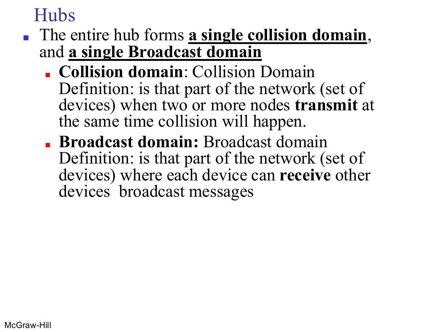
Collision domain: the set of devices whose simultaneous SENDING collides.
Memory trick Collision = who can crash into each other. Broadcast = who can hear each other’s shouting.
Exam angle
Five PCs are connected to one hub. How many collision domains?
Define collision domain and broadcast domain.
Compare with the model answer
A collision domain is the part of a network where two devices sending at the same time collide. A broadcast domain is the part where every device receives the others’ broadcast messages.
Interconnecting with hubs
Notes
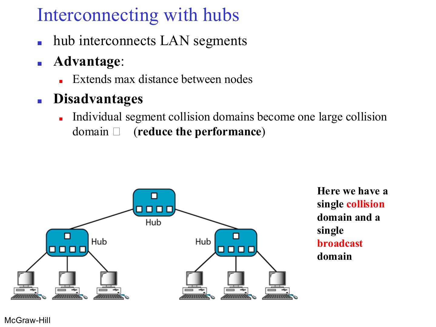
Hubs joined by a hub: longer reach, but ALL the segments become one big collision domain → worse performance.
Link-Layer Switches
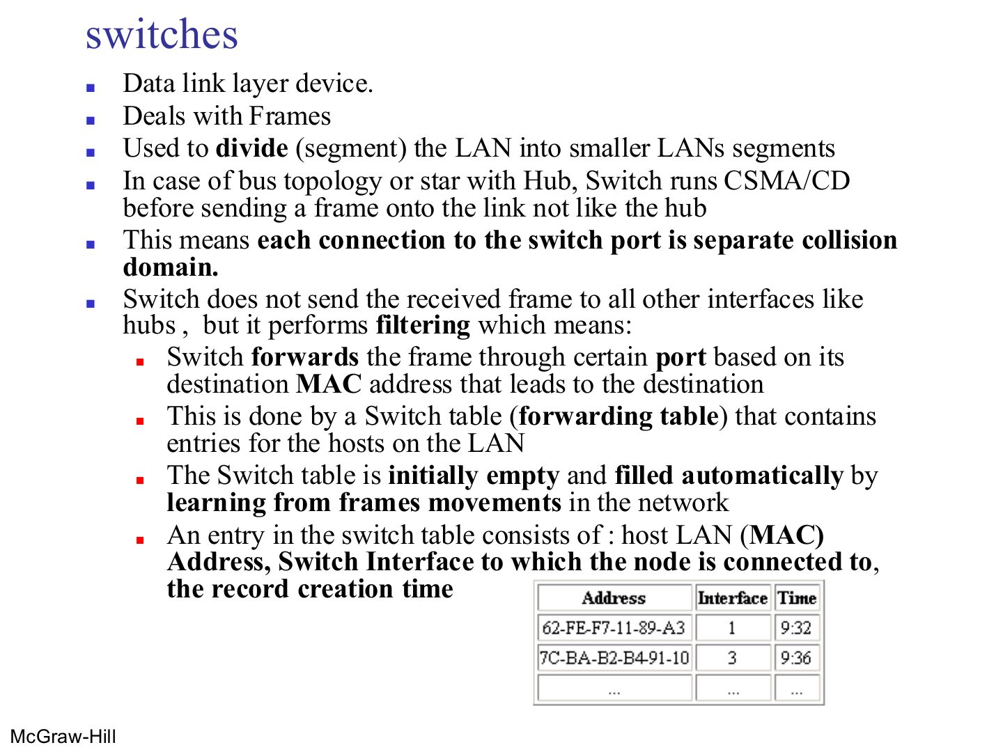
Switches
Notes
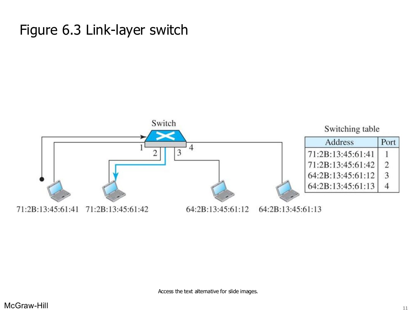
The table starts EMPTY and fills itself by learning. Entry = MAC address + interface + time.
Exam angle
A switch’s forwarding table is initially:
A switch table entry contains:
Switches vs. hubs
Link-layer switch
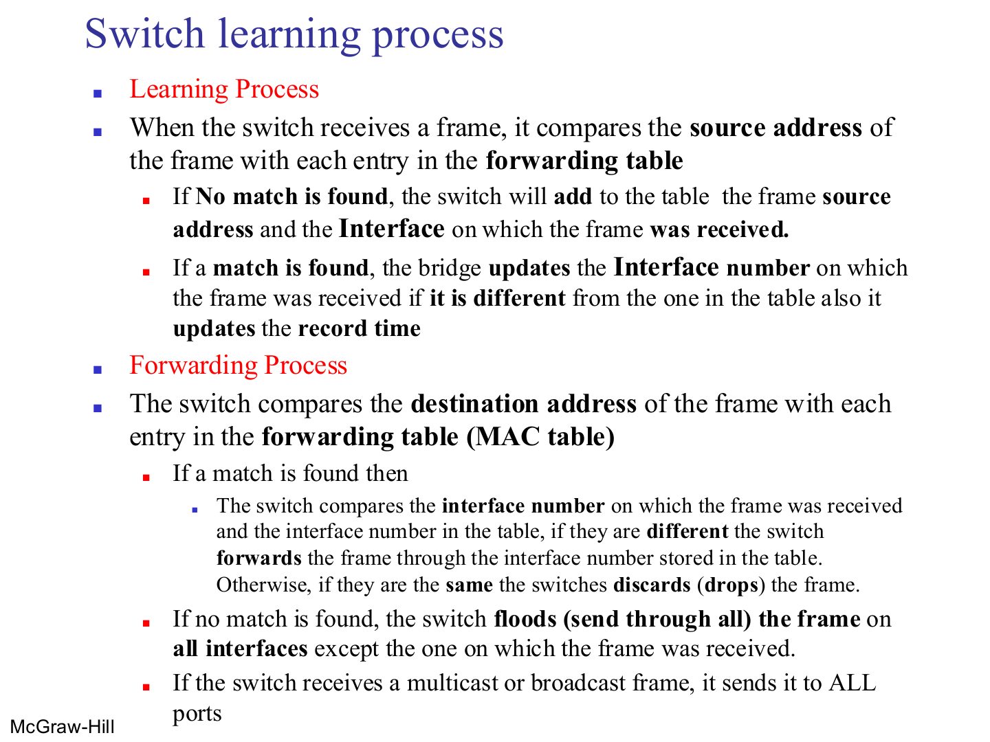
Switch learning process
Notes
Destination known → forward out of that port (or drop if it’s the same port it came in on). Unknown → flood. Broadcast/multicast → all ports.
Memory trick Source teaches, destination decides.
Trap A switch never learns from the destination address.
Exam angle
A switch learns a new table entry from a frame’s:
A switch receives a frame whose destination MAC is not in its table. It:
If the destination is on the same port the frame arrived on, the switch drops the frame.
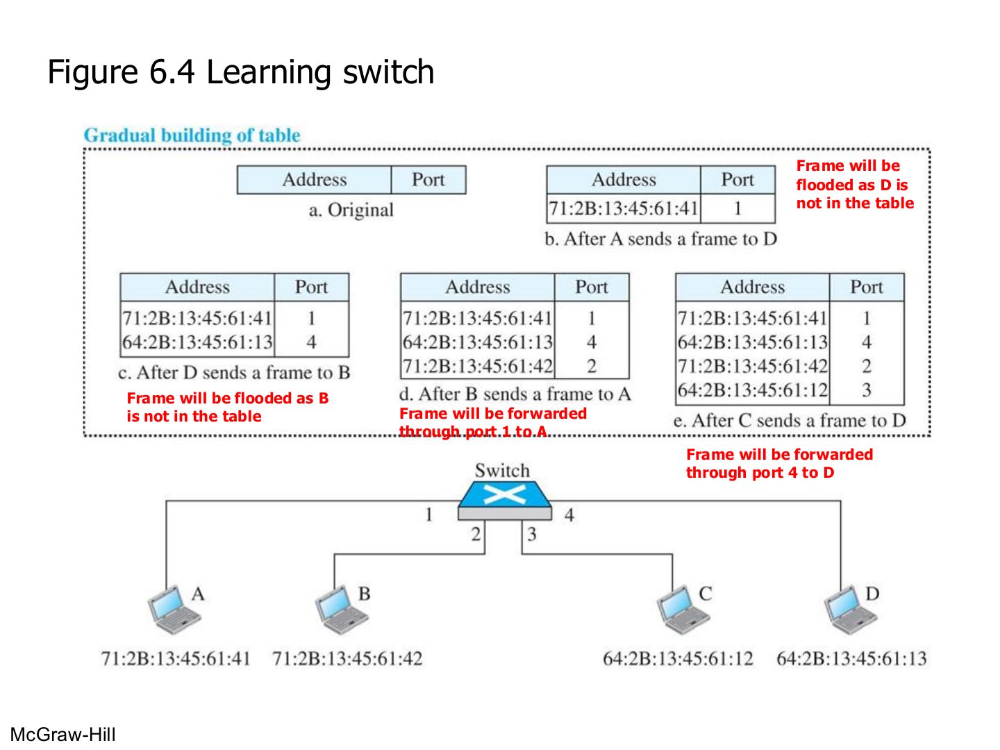
Learning switch (Figure 6.4)
Notes
a. Empty. b. A → D: learn A on port 1; D unknown → flood. c. D → B: learn D on port 4; flood. d. B → A: learn B; A known → port 1. e. C → D: learn C; D known → port 4.
Exam angle
An empty switch has A on port 1, B on port 2, C on port 3, D on port 4. A sends to D, then D sends to A. What does the switch do each time?
Compare with the model answer
A → D: it learns “A is on port 1”; D is unknown, so it floods the frame to ports 2, 3 and 4. D → A: it learns “D is on port 4”; A is known, so it forwards only out of port 1.
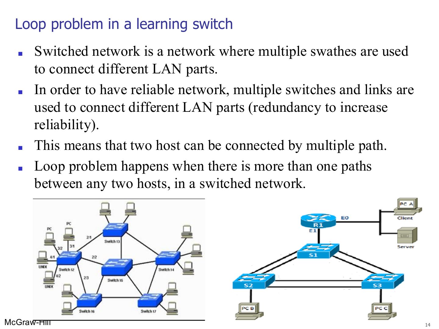
Loop problem in a learning switch
Loop problem in a learning switch
Notes
Broadcast, multicast and unknown-unicast frames get flooded; with a loop they go round forever and multiply → broadcast storm → the network dies.
Exam angle
Loops in a switched network cause:
Which protocol removes loops from a switched network?
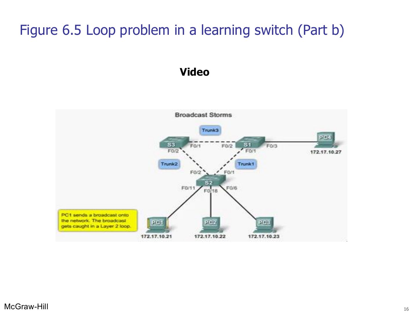
Loop problem in a learning switch: broadcast storm
Notes
The same broadcast keeps circling the triangle of switches.
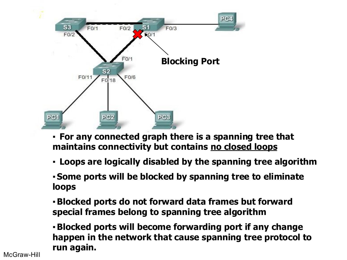
Spanning tree: blocking ports
Notes
STP keeps every switch reachable but BLOCKS some ports so no loop is left.
Blocked ports still pass STP’s own frames, and wake up if the topology changes (backup paths).
Trap STP doesn’t remove cables; it logically blocks ports.
Exam angle
Ports blocked by spanning tree forward no frames at all.
- They still carry the spanning tree’s own frames.
A blocked port can become a forwarding port again if the network changes.
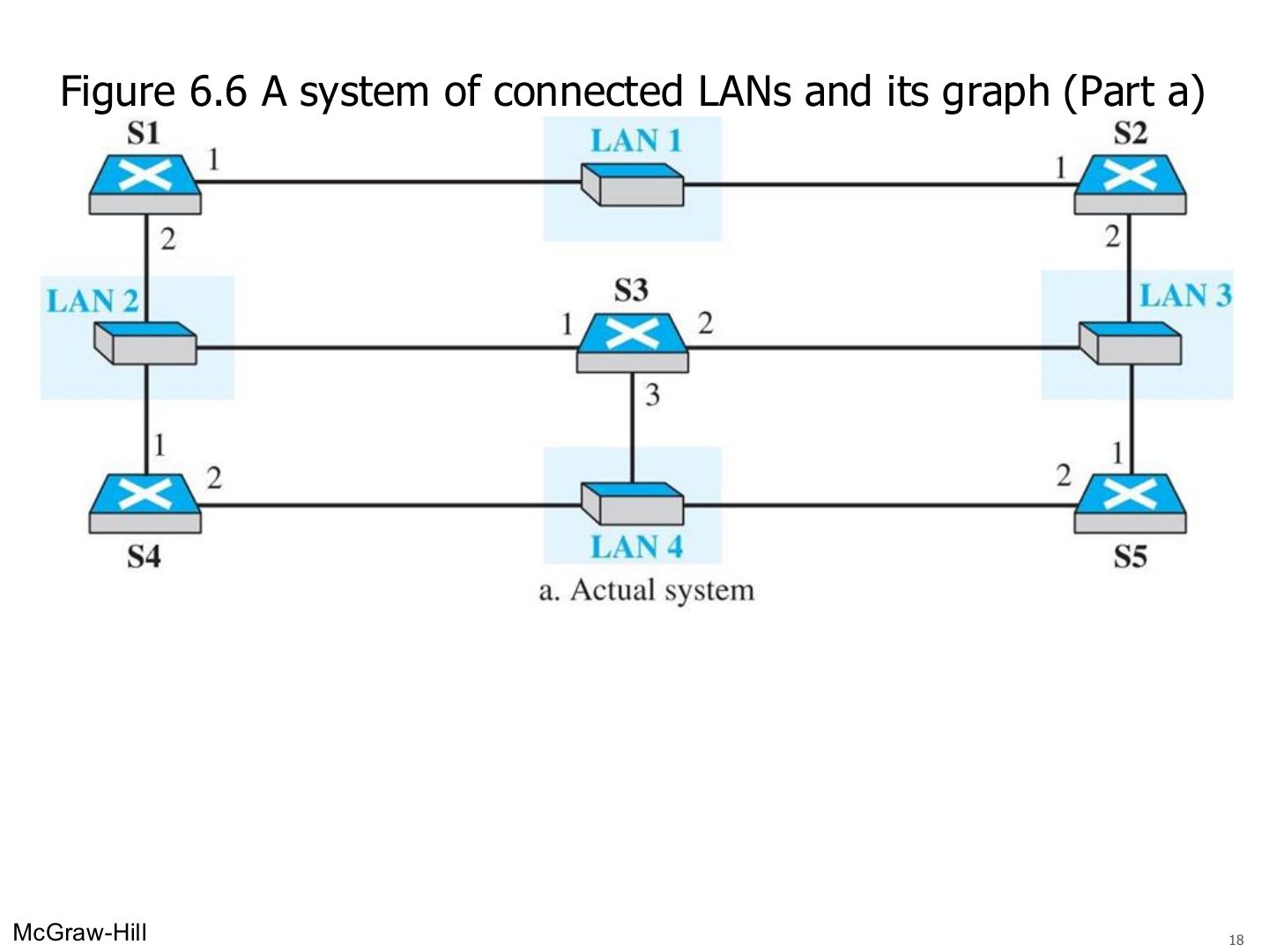
A system of connected LANs and its graph (Part a) (Figure 6.6)
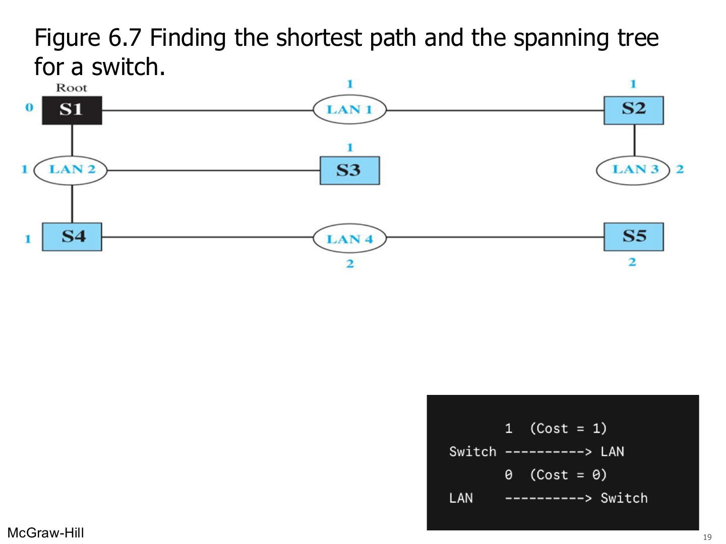
Finding the shortest path and the spanning tree for a switch. (Figure 6.7)
Notes
Pick a root bridge (S1), then keep the shortest path from every switch to the root.
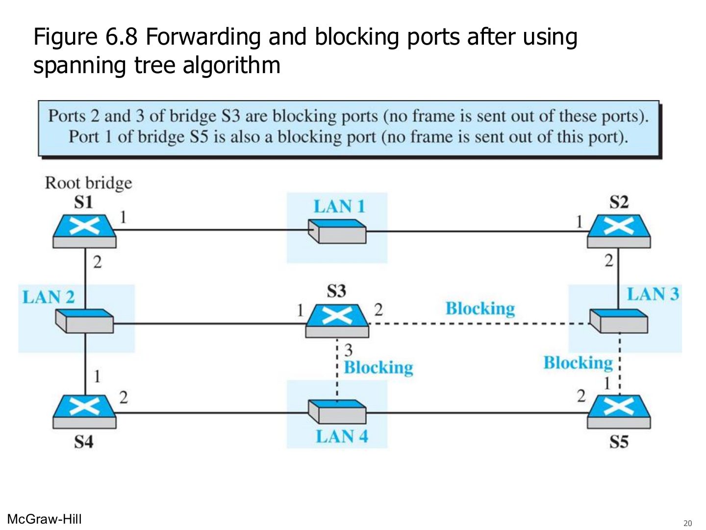
Forwarding and blocking ports after using spanning tree algorithm (Figure 6.8)
Notes
Blocked: S3 ports 2 and 3, S5 port 1. No frame goes out of them.
Some switch features
Notes
Better performance and security (traffic only goes where needed), no size limit, transparent and plug-and-play.
Exam angle
A network of switches with no VLANs forms how many broadcast domains?
A switch isolates broadcast domains.
- Only collision domains. Routers (or VLANs) isolate broadcast domains.
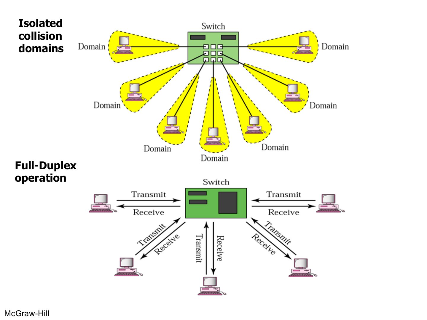
Isolated collision domains
Notes
Every port = its own collision domain; with full duplex there are no collisions at all.
Seen again Ch 4, slide 25: Collision domains in switched Ethernet
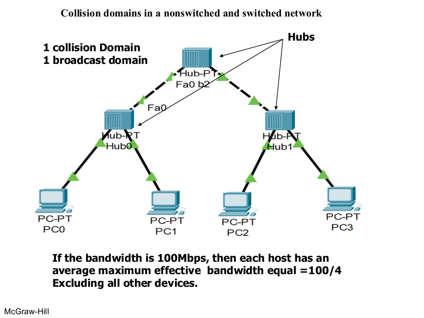
Collision domains in a nonswitched and switched network
Notes
Hubs only: 1 collision domain, 1 broadcast domain. 4 hosts share 100 Mbps → 25 Mbps each.
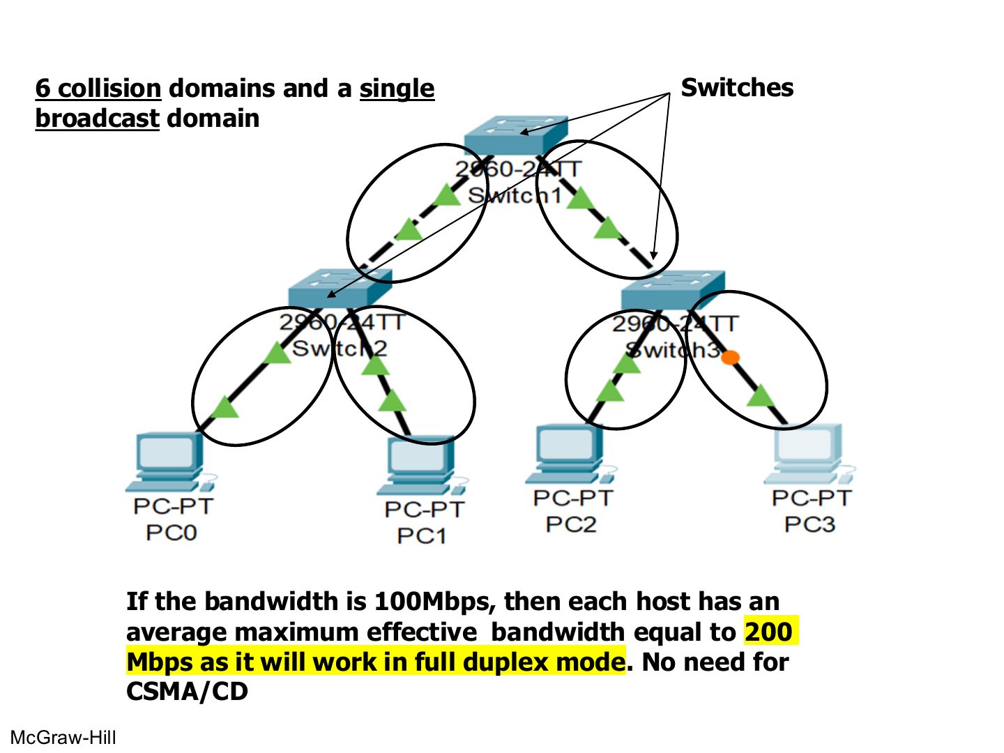
Collision domains in a switched network
Notes
Count the LINKS between switch ports and devices: 6 links → 6 collision domains. No router → 1 broadcast domain.
Each host gets the full 100 Mbps each way (200 Mbps full duplex).
Exam angle
A hub-based LAN of 4 hosts on 100 Mbps gives each host about:
The same 4 hosts on full-duplex switches each get up to:
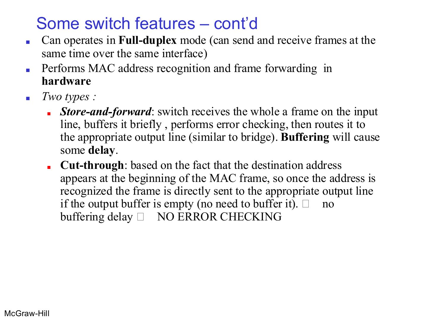
Some switch features – cont’d
Notes
Cut-through: start sending as soon as the destination address is read → fast, but no error checking.
Memory trick Store-and-forward = Safe but Slow. Cut-through = Quick but Careless.
Exam angle
Which switching type checks the frame for errors before forwarding?
Cut-through switching starts forwarding after reading the:
Routers
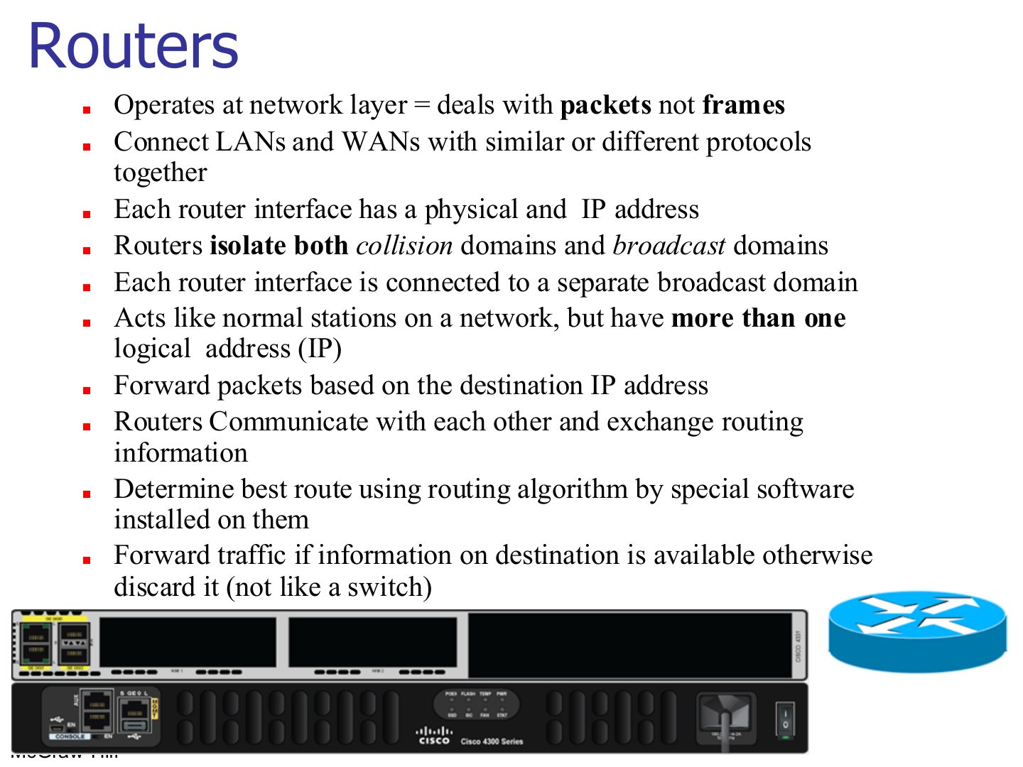
Notes
Seen again Ch 8, slide 3: How routers build their tables
Exam angle
Which device isolates both collision and broadcast domains?
A router floods a packet whose destination is not in its routing table.
- It discards it; flooding is what a switch does.
Routing example
Notes
Broadcast domains = router interfaces in use (2). Collision domains = every switch/router link (9).
Typical Organization LAN
Notes
Count router interfaces with something behind them: 4 → 4 broadcast domains.
Tip Counting domains: every switch or router PORT starts a new collision domain (a hub port does not). Every router PORT starts a new broadcast domain (switches and hubs do not, unless VLANs are used).
Exam angle
A router has 3 interfaces. Interface 1 goes to a switch with 5 PCs, interface 2 to a hub with 4 PCs, interface 3 to the Internet. Count the broadcast and collision domains (ignore the Internet side).
Compare with the model answer
Broadcast domains: 2 (one per LAN interface). Collision domains: the switch side has 5 (one per PC link) + 1 (switch–router link) = 6; the hub side is 1 (hub and all its PCs plus the router link). Total 7.
Comparison between switch and router
Notes
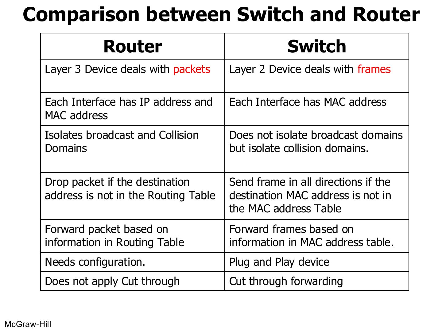
Learn this table: it is the most likely written comparison in the chapter.
Exam angle
Give four differences between a switch and a router.
Compare with the model answer
Layer: switch layer 2 (frames), router layer 3 (packets). Addresses: switch ports have MACs; router interfaces have IP and MAC. Domains: switch isolates collision domains only, router isolates collision and broadcast domains. Unknown destination: switch floods, router drops. Setup: switch is plug-and-play, router needs configuration. Switches can cut through; routers don’t.
Virtual LANs
Notes
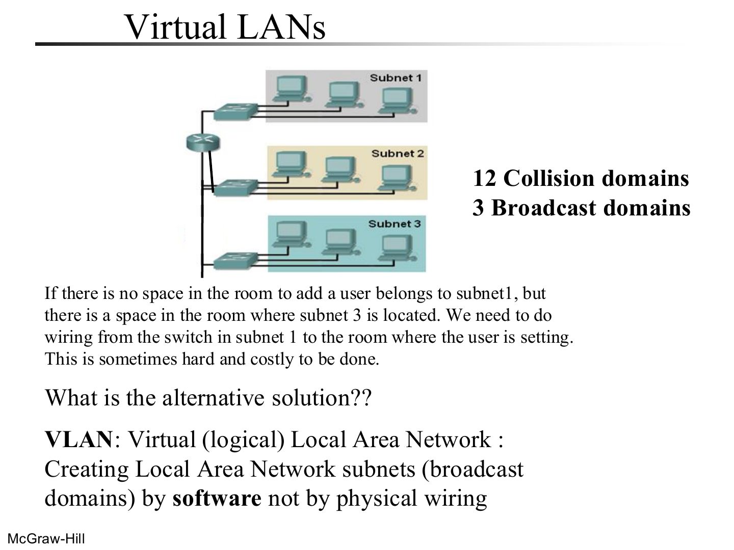
Problem: moving a user to another subnet means new wiring.
Exam angle
A VLAN creates subnets (broadcast domains) by:
A switch using VLAN software
Notes
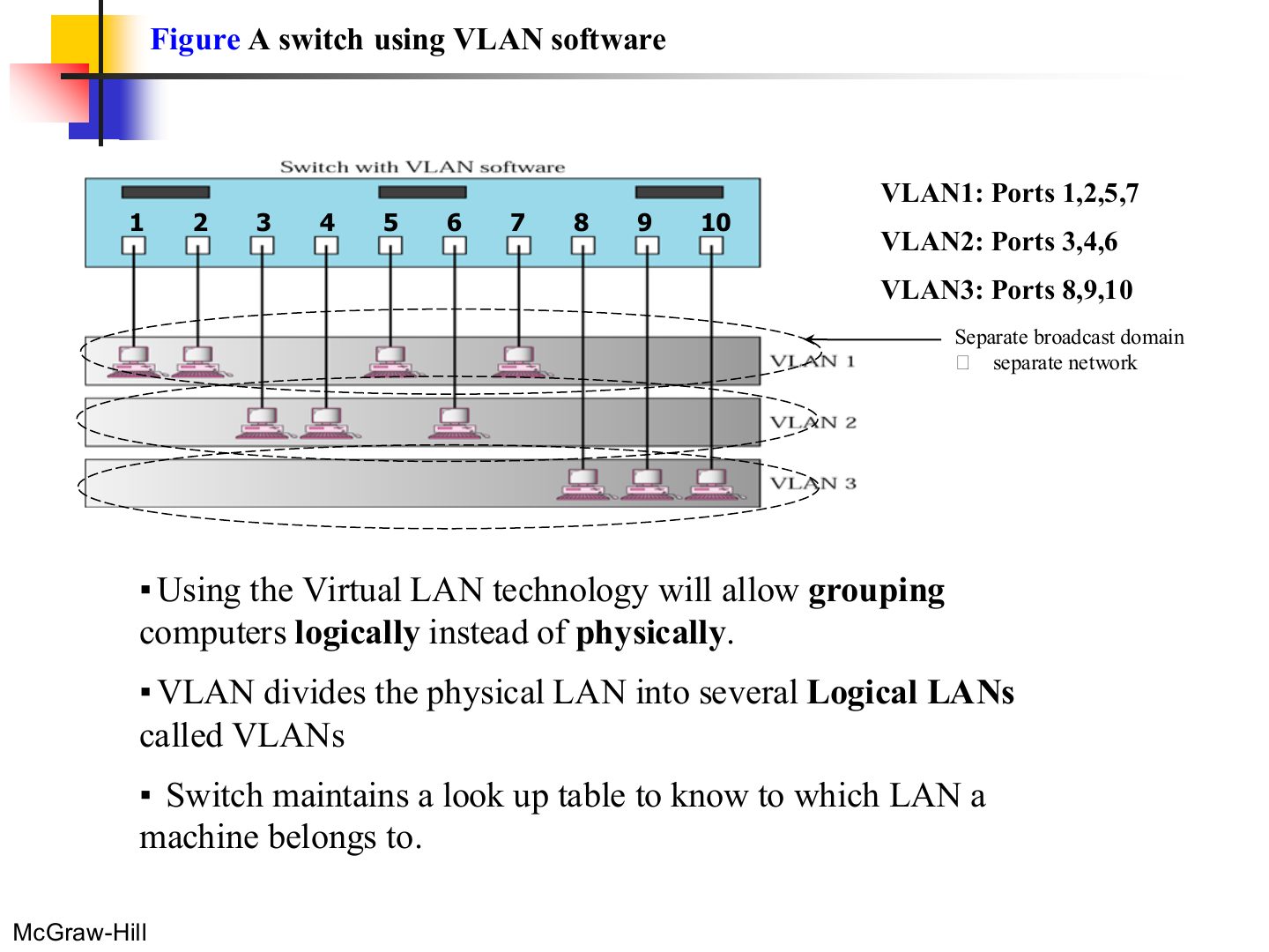
One physical switch, three logical LANs. Each VLAN = its own broadcast domain = its own network.
Exam angle
One switch is split into 3 VLANs. How many broadcast domains does it have?
Two switches in a backbone using VLAN software (Figure 6.12)
Notes
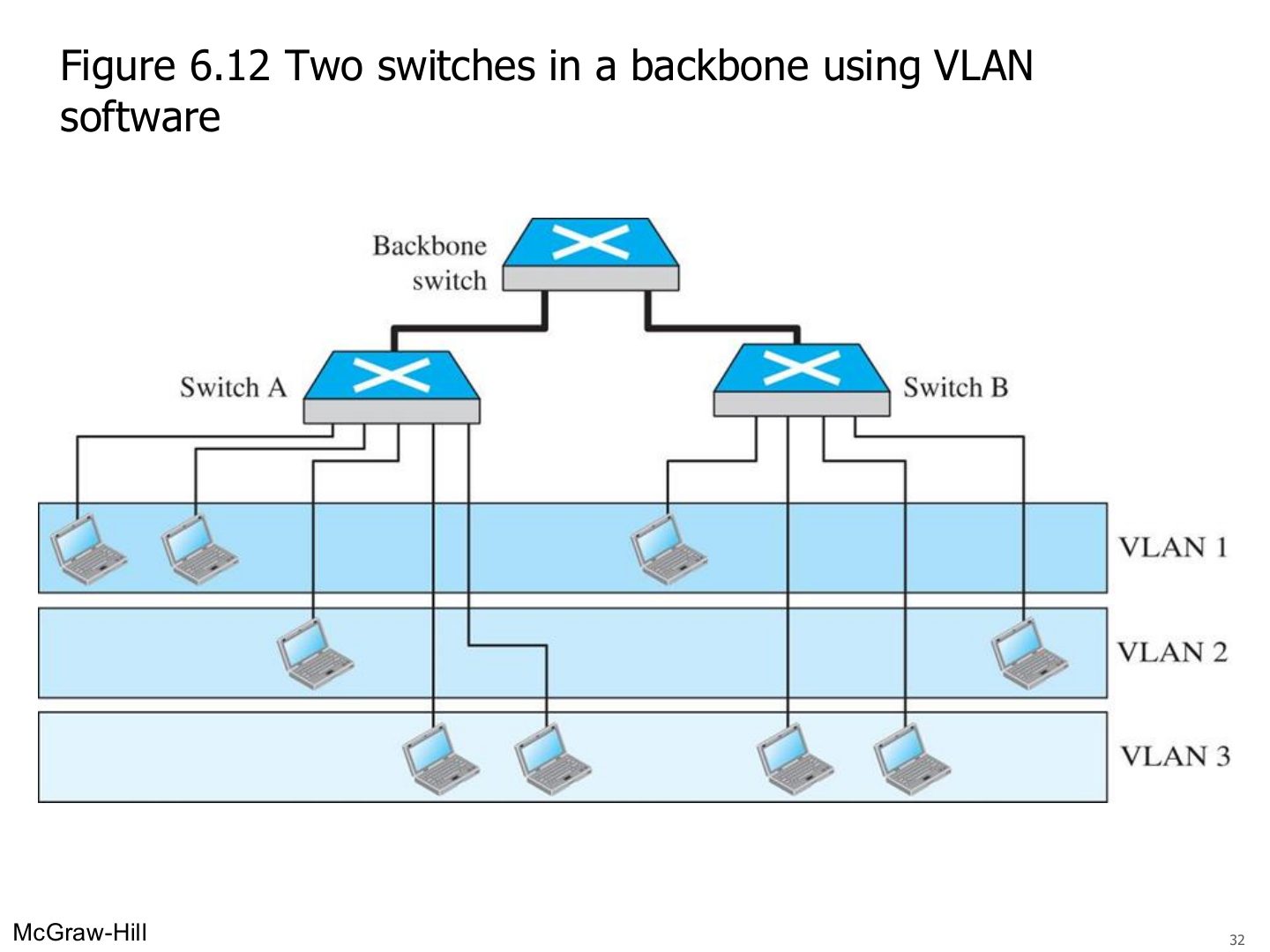
VLANs can span several switches: members of VLAN 1 can sit on switch A and switch B.
Note: VLANs create broadcast domains
Notes
VLANs = broadcast domains. That one line answers many MCQs.
Exam angle
VLANs create separate broadcast domains on the same switch.
Advantages Of VLAN
Notes
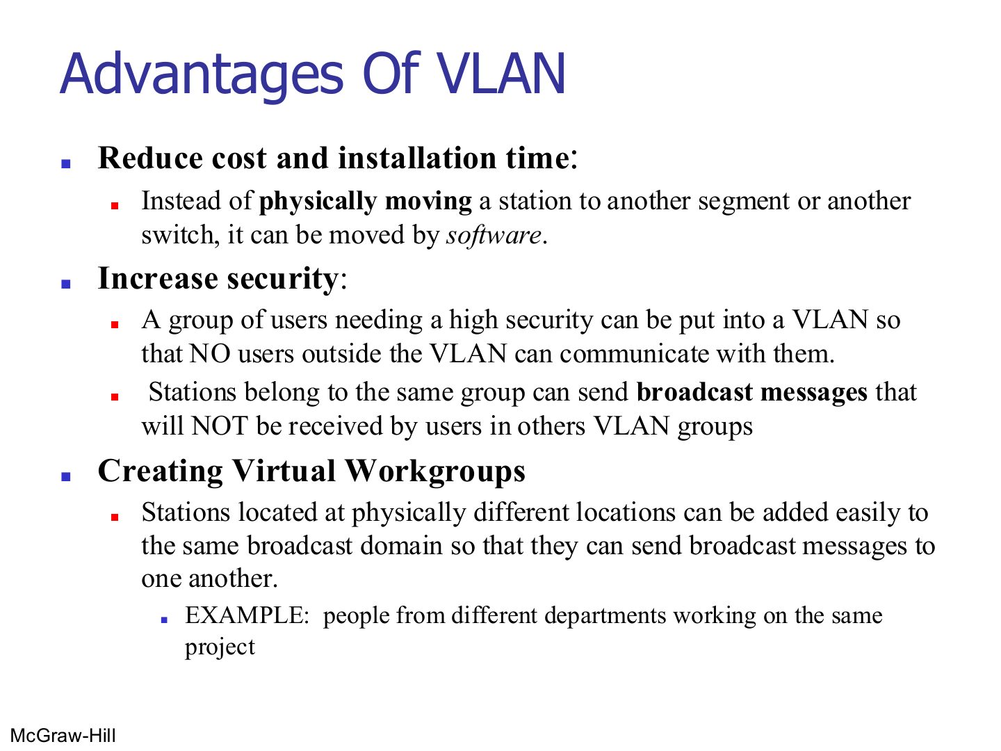
VLAN advantages: cheaper moves (software, not wiring), security (broadcasts stay inside the VLAN), virtual workgroups across locations.
Exam angle
Give three advantages of VLANs.
Compare with the model answer
Lower cost and installation time, because moving a station is done in software; more security, since a group can be isolated and its broadcasts are not seen by other VLANs; and virtual workgroups, where people in different places (for example a cross-department project team) share one broadcast domain.