Making sure the sender does not send faster than the receiver can process is:
Data Link Layer: Framing and Error Control
What the data link layer does, how frames are marked off (byte and bit stuffing), single-bit vs. burst errors, and the three detection methods: parity (simple and two-dimensional), CRC and the Internet checksum, then retransmission vs. forward error correction. Tutorial 4 is entirely parity, CRC and checksum calculations; the worked answers are in the questions on each method’s slides.
How to read this page
Every original slide is shown unchanged. Yellow marks on a slide point to a numbered note: hover or tap a mark to jump to its note, and hover a note to see its marks. Questions tagged Past exam appeared on a real paper; Prediction questions are likely angles, not confirmed. Pick an answer to each question: a wrong pick tells you why it is wrong, so you can try again.
All 53 slides
- 1 Data-Link Layer
- 2 Chapter 3: Outline
- 3 Chapter 3 DLL services
- 4 Framing
- 5 DLL services
- 6 Framing
- 7 A frame in a character-oriented protocol
- 8 Byte stuffing and unstuffing
- 9 A frame in a bit-oriented protocol
- 10 Bit stuffing and unstuffing
- 11 Note: errors happen
- 12 Types of error
- 13 Note: single-bit error
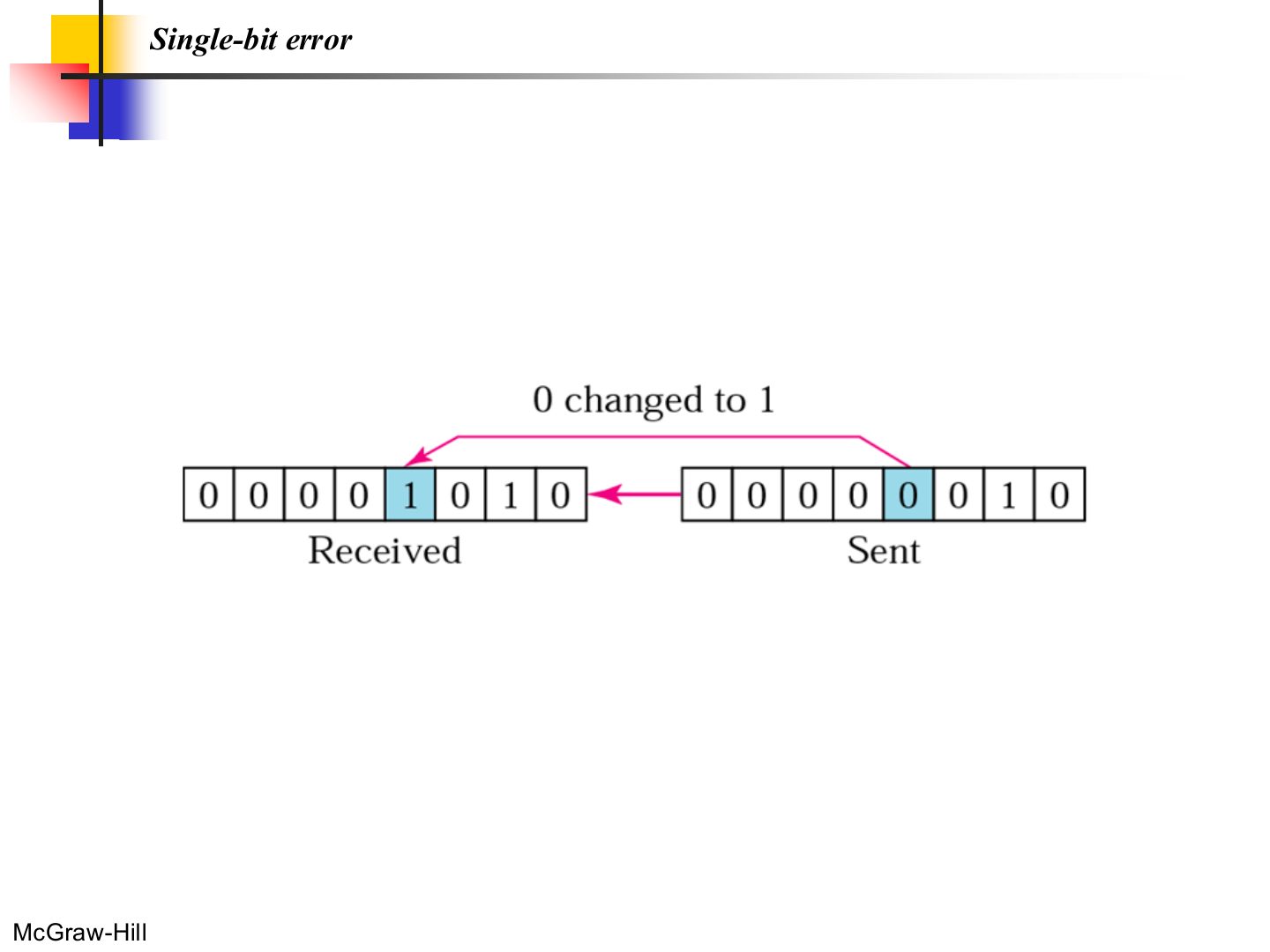
- 14 Single-bit error
- 15 Note: burst error
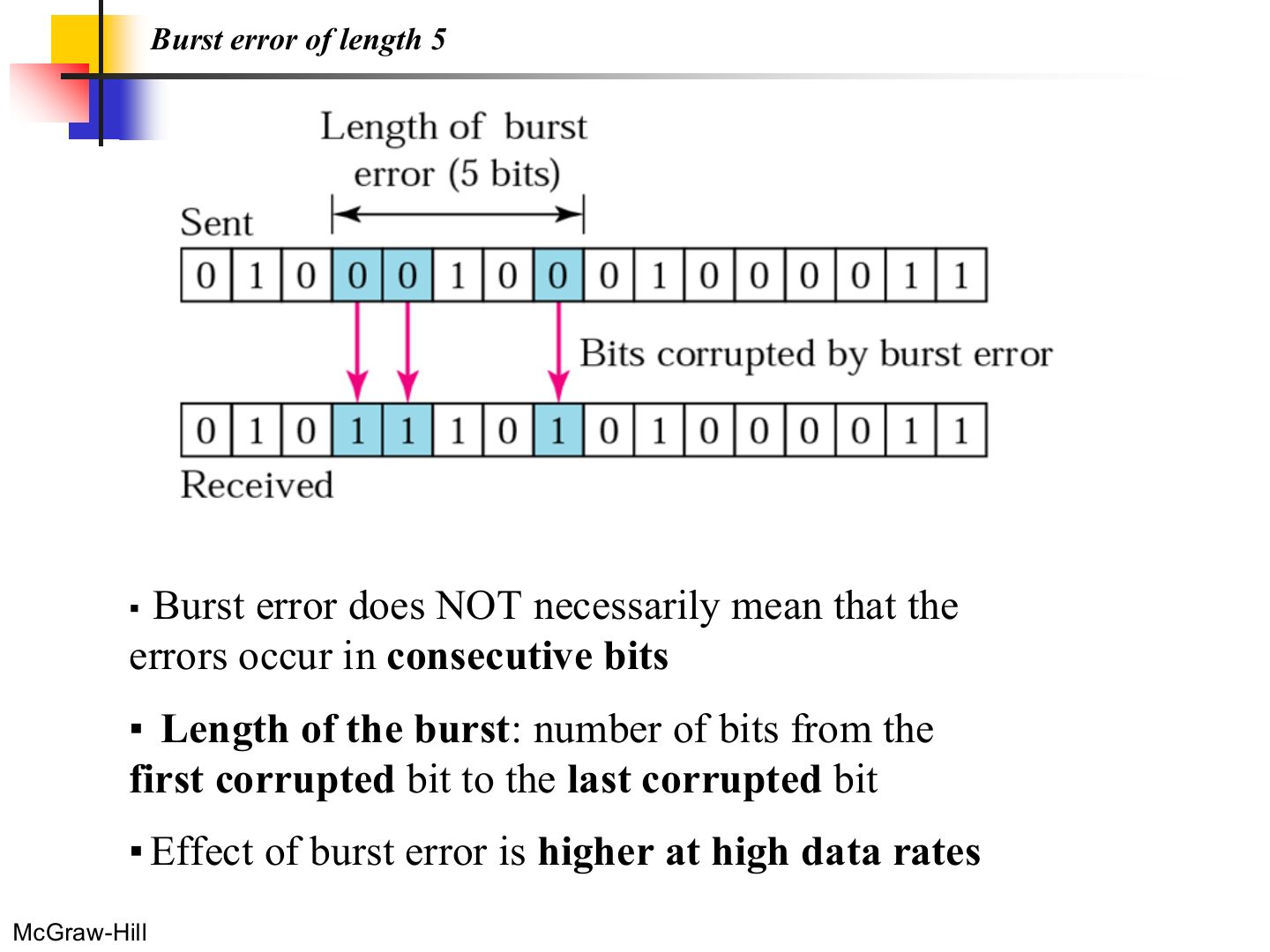
- 16 Burst error of length 5
- 17 Example
- 18 Note: redundancy
- 19 Detection methods
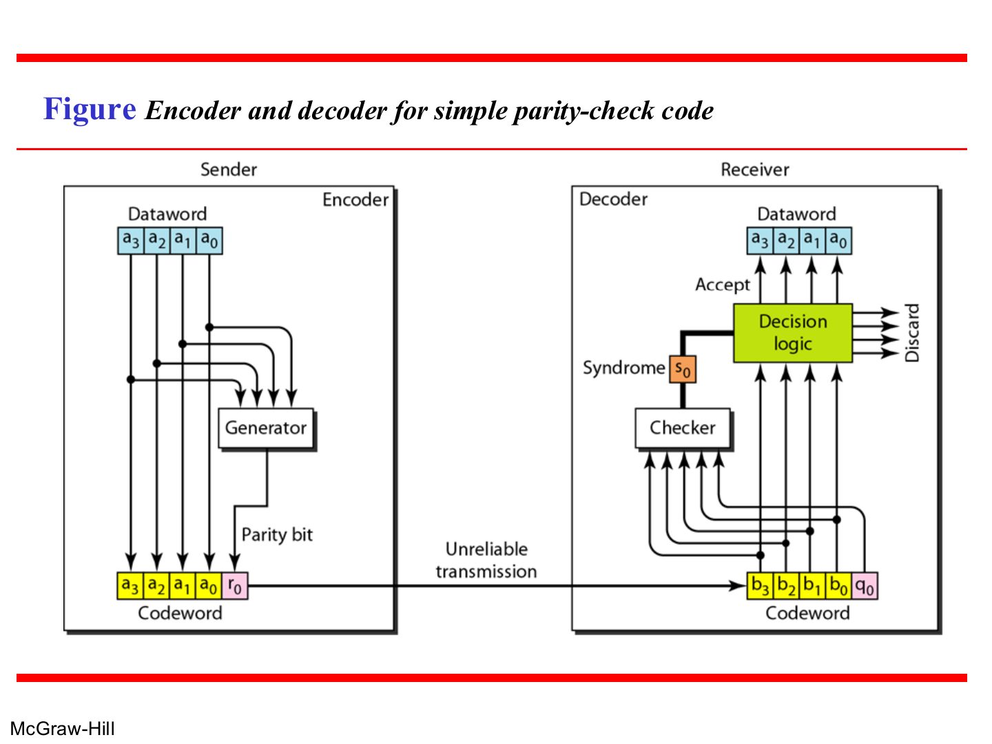
- 20 The structure of encoder and decoder
- 21 Encoder and decoder for simple parity-check code
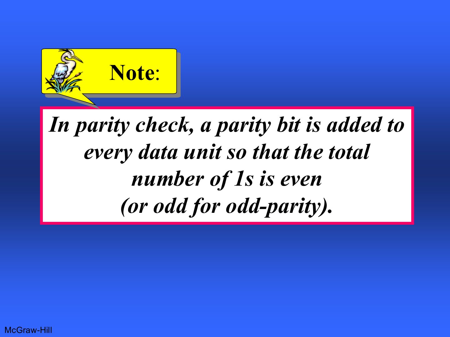
- 22 Note: parity check
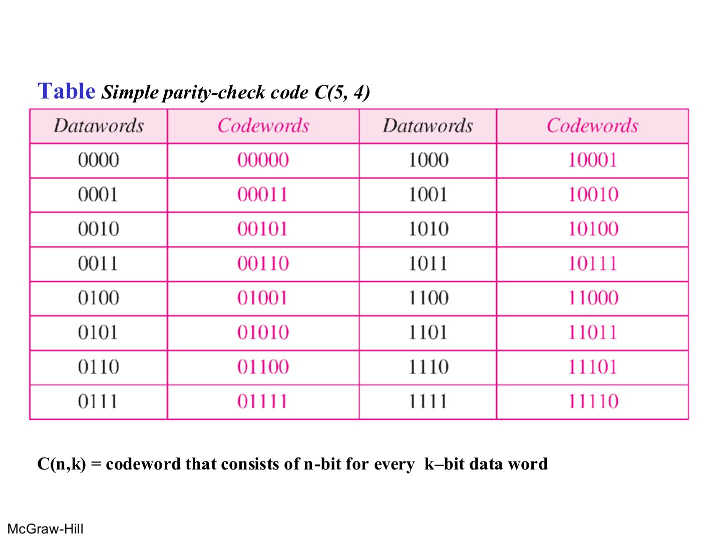
- 23 Table Simple parity-check code C(5, 4)
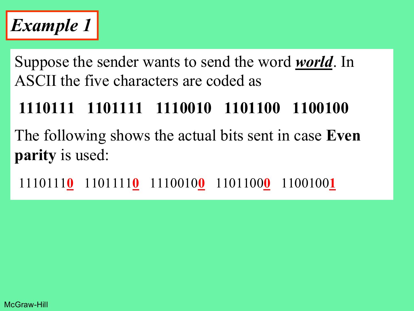
- 24 Example 1
- 25 Example 2
- 26 Example 3
- 27 Note: what simple parity can detect
- 28 Note: two-dimensional parity
- 29 Two-dimensional parity
- 30 Two-dimensional parity: what it detects
- 31 CRC generator and checker
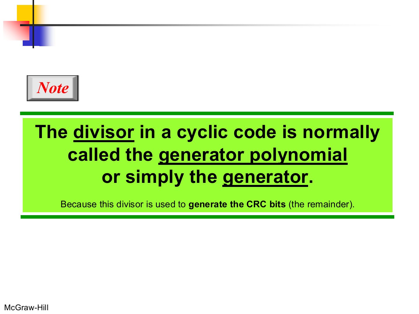
- 32 Note: the generator
- 33 A polynomial to represent a binary word
- 34 Division in CRC encoder
- 35 Division in the CRC decoder for two cases
- 36 Binary division in CRC checker
- 37 CRC summary
- 38 Standard polynomials
- 39 Advantages of Cyclic Codes
- 40 Example
- 41 Example (continued)
- 42 Checksum
- 43 Data unit and checksum
- 44 Checksum: sender site
- 45 Checksum: receiver site
- 46 Example 7
- 47 Example 8
- 48 Example 9
- 49 Error correction
- 50 Error correction 1: retransmission
- 51 Error correction 2: forward error correction (FEC)
- 52 Burst Error Correction Chunk Interleaving
- 53 Interleaving
Data-Link Layer
Notes
DLL services → framing (byte / bit stuffing) → error types → detection: parity, 2D parity, CRC, checksum → correction.
Tutorial 4 = calculations on parity, CRC and checksum. Practise each by hand.
Chapter 3: Outline
Notes
This part is 3.1 introduction and 3.2 data link control (framing, error control). Part 2 is 3.3 media access control.
Chapter 3 DLL services
Notes
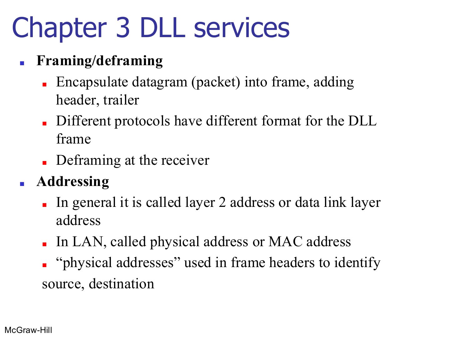
Seen again Ch 1 Part 2, slide 28: Data link layer overview
Framing
Notes
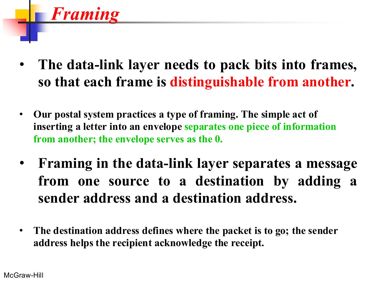
Framing = packing bits into frames so the receiver knows where each one starts and ends (like envelopes).
The destination address says where it goes; the sender address lets the receiver acknowledge it.
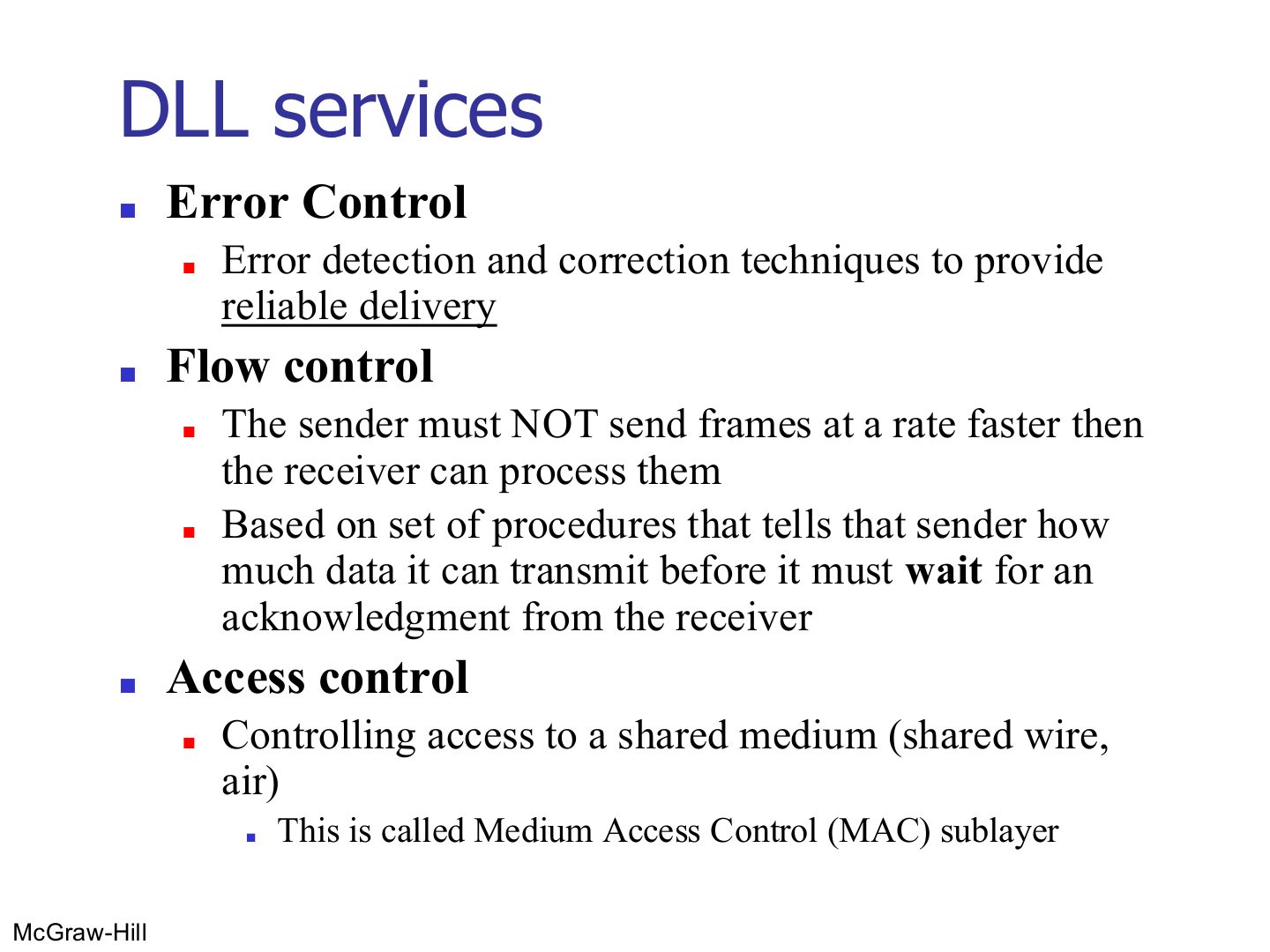
DLL services
Notes
Trap Flow control protects the RECEIVER from being flooded; congestion control (Ch 9) protects the NETWORK.
Seen again Ch 3 Part 2, slide 2: Media access control
Seen again Ch 9, slide 6: Flow and error control at the transport layer
Exam angle
Controlling access to a shared medium is done by the:
Framing
Notes
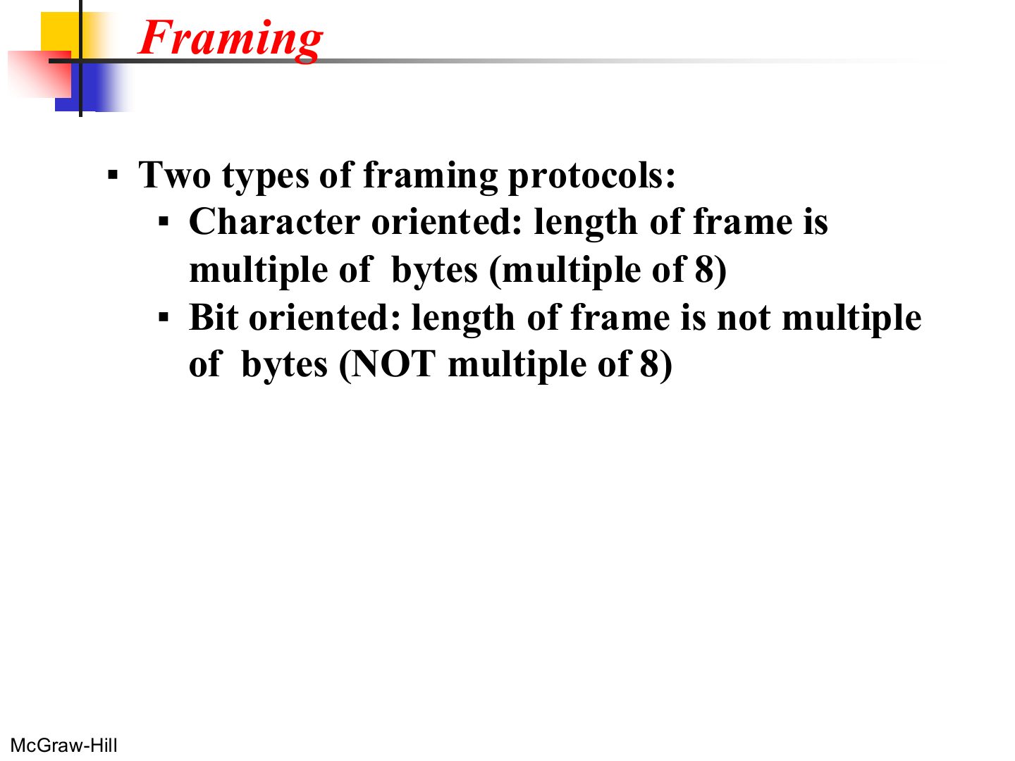
Character (byte) oriented: frame length is a whole number of bytes. Bit oriented: any number of bits.
Exam angle
A framing protocol whose frame length need not be a multiple of 8 bits is:
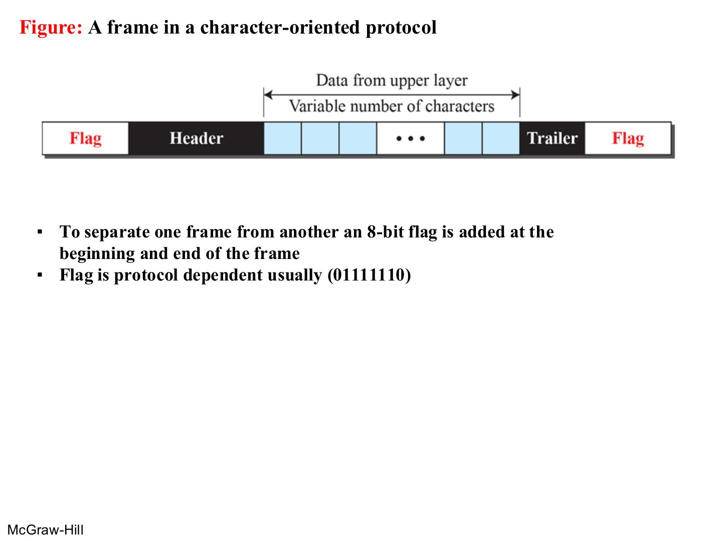
A frame in a character-oriented protocol
Notes
A flag byte marks the start and end of every frame.
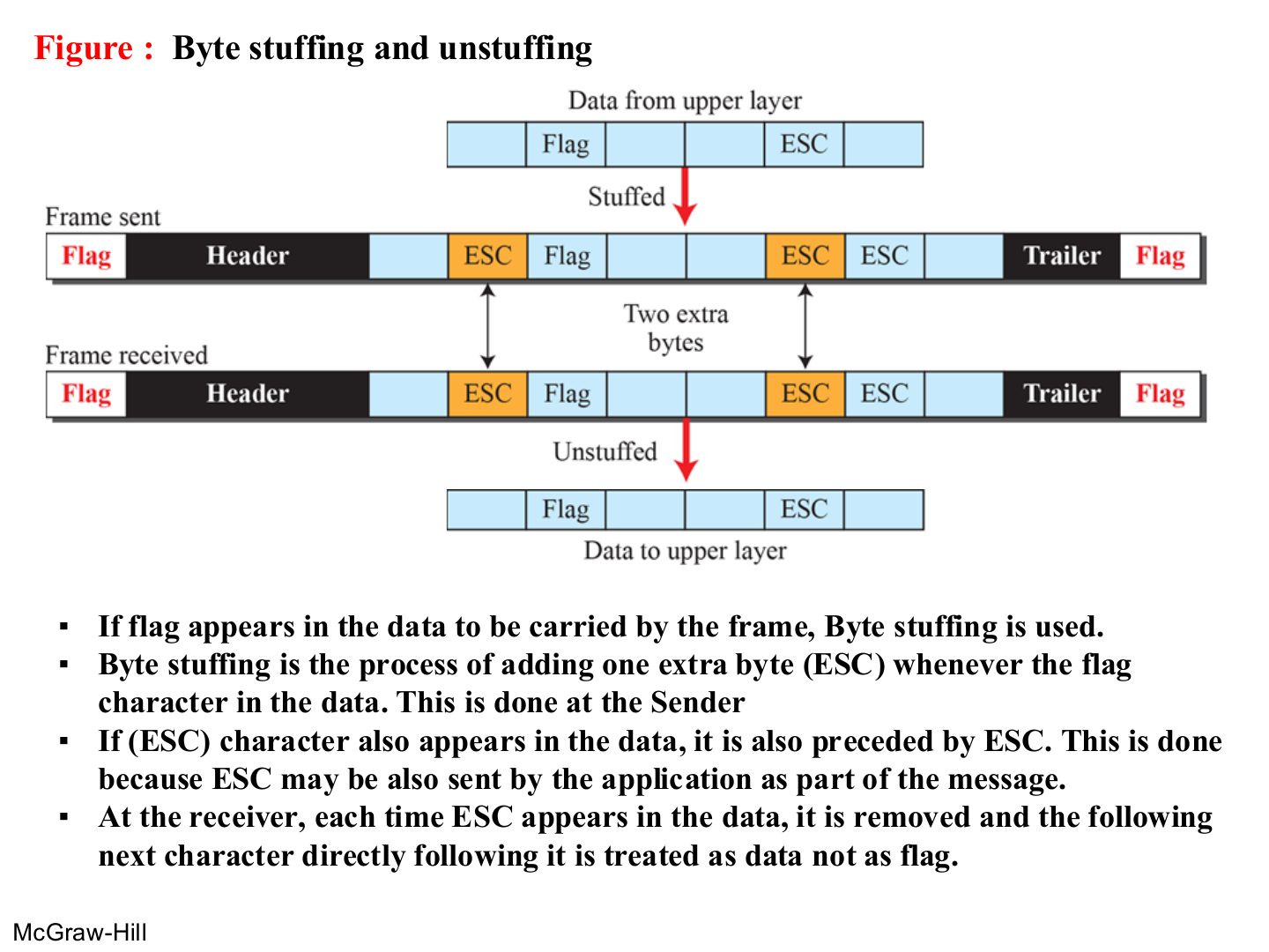
Byte stuffing and unstuffing
Notes
Problem: the flag pattern can appear inside the data.
Trap ESC itself must also be escaped, or the receiver would drop a real ESC byte from the data.
Exam angle
In byte stuffing, the sender adds an extra ESC byte:
Byte stuffing is done at the receiver.
- Stuffing is done by the sender; the receiver unstuffs.
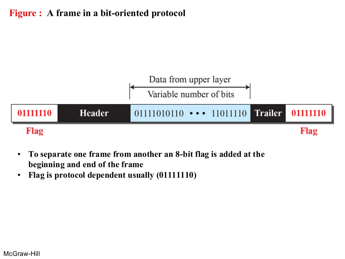
A frame in a bit-oriented protocol
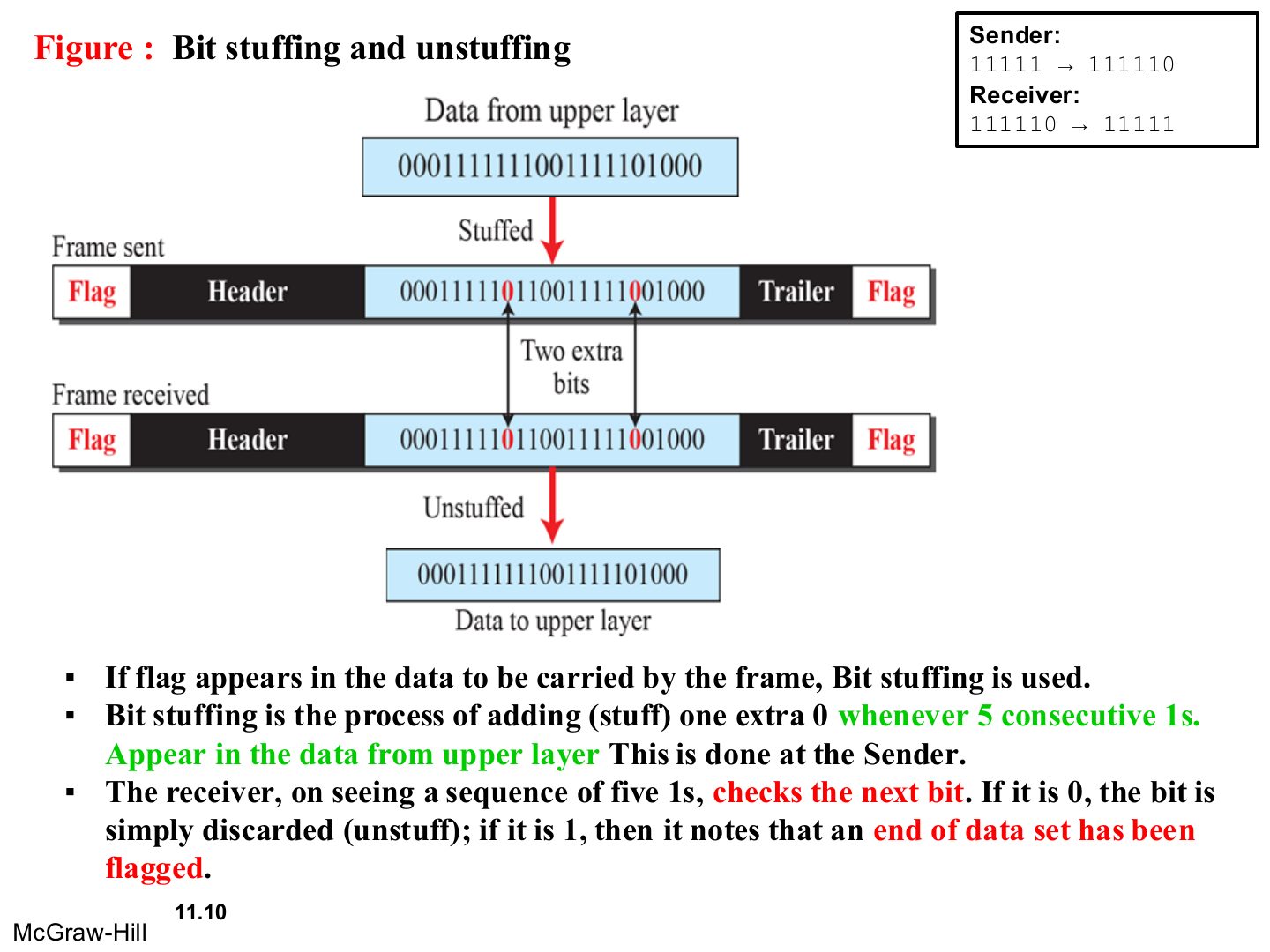
Bit stuffing and unstuffing
Notes
After five 1s in a row, the sender always inserts a 0, even if the next bit is already 0. So 01111110 can never appear in the data.
Memory trick Count to five 1s, then add a 0. Restart the count after the stuffed 0.
Exam angle
After bit stuffing, the data 0111111 becomes:
- Five 1s → add a 0, then the sixth 1 follows.
Bit stuffing inserts a 0 after how many consecutive 1s?
Stuff the bits 0001111111001111101000 for transmission with flag 01111110.
Compare with the model answer
000111110110011111001000: a 0 goes in after the first five 1s of the 1111111 run and after the five 1s of 11111.
Note: errors happen
Types of error
Note: single-bit error
Single-bit error
Note: burst error
Notes
Burst: TWO or more bits changed (not necessarily next to each other).
Burst error of length 5
Notes
Burst length = from the first corrupted bit to the last, counting the good bits in between.
The faster the link, the more bits a burst of noise hits.
Trap A burst of length 5 may corrupt only 3 bits: the length counts from first to last bad bit.
Exam angle
In a burst error, the corrupted bits must be consecutive.
Bits 3 and 9 of a frame are corrupted and nothing in between. The burst length is:
- 9 - 3 + 1 = 7.
Example
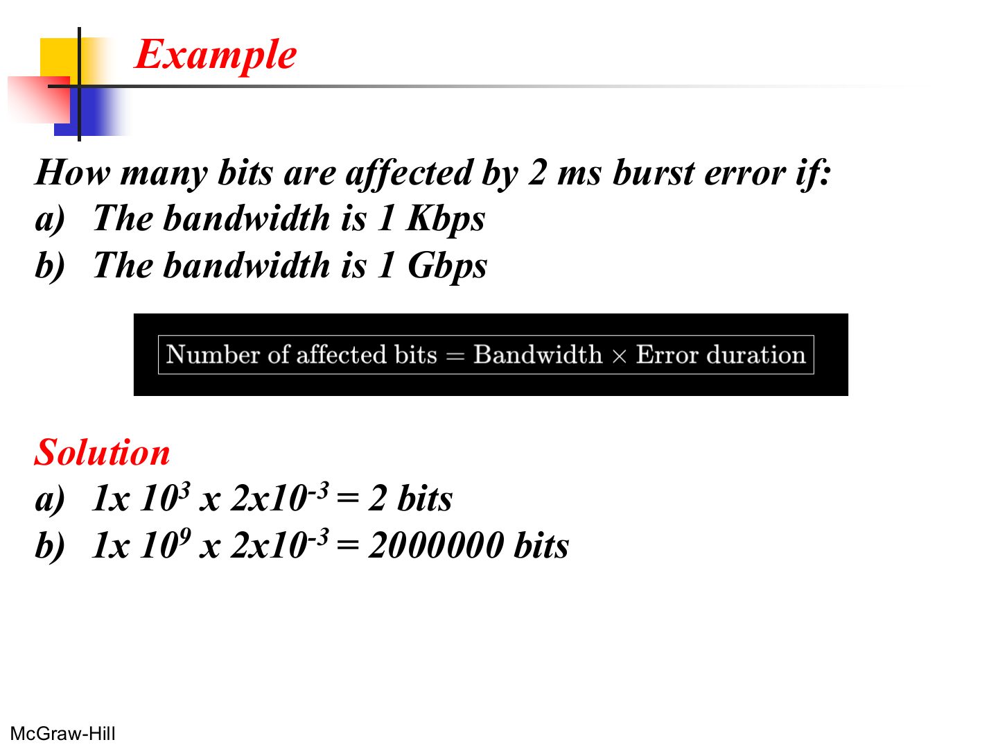
Notes
Same 2 ms of noise: 2 bits on a slow link, 2 million on a fast one. That is why burst errors are worse at high rates.
Exam angle
A 5 ms burst of noise hits a 100 Mbps link. How many bits are affected?
- 10⁸ × 5 × 10⁻³.
Note: redundancy
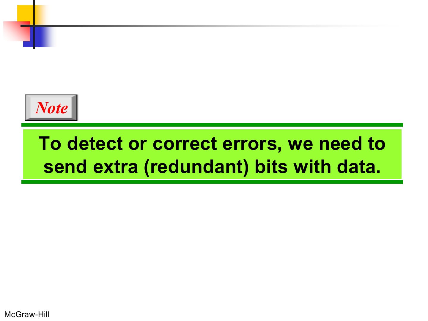
Notes
Every detection method sends EXTRA (redundant) bits along with the data.
Detection methods
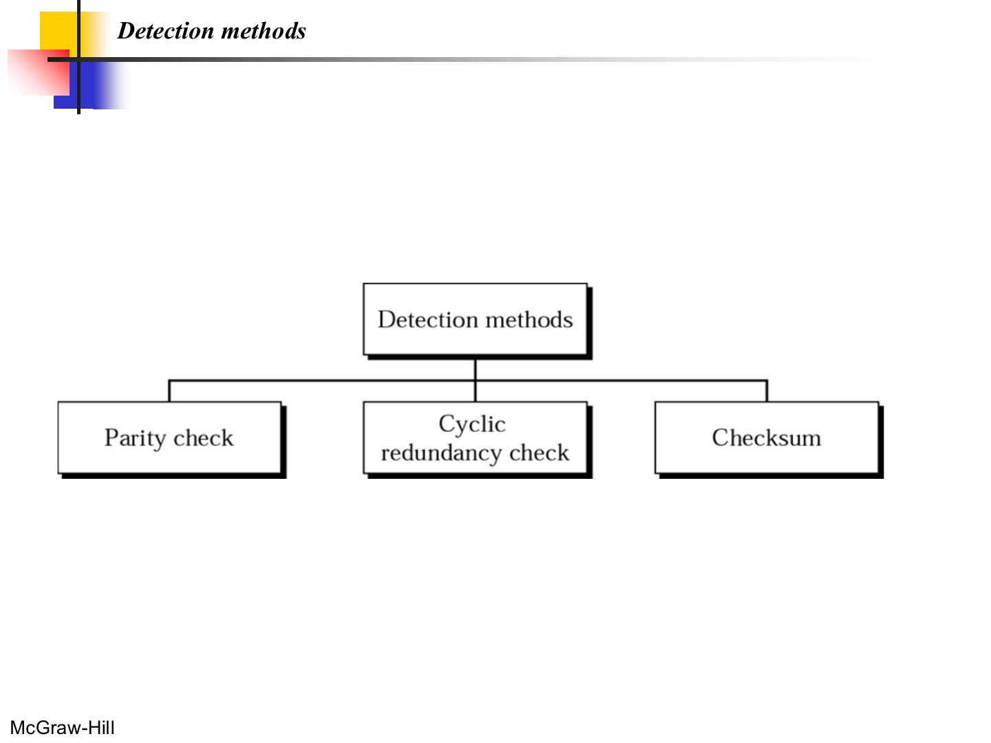
Notes
Parity check · CRC · checksum.
Exam angle
Which is NOT an error-detection method?
The structure of encoder and decoder
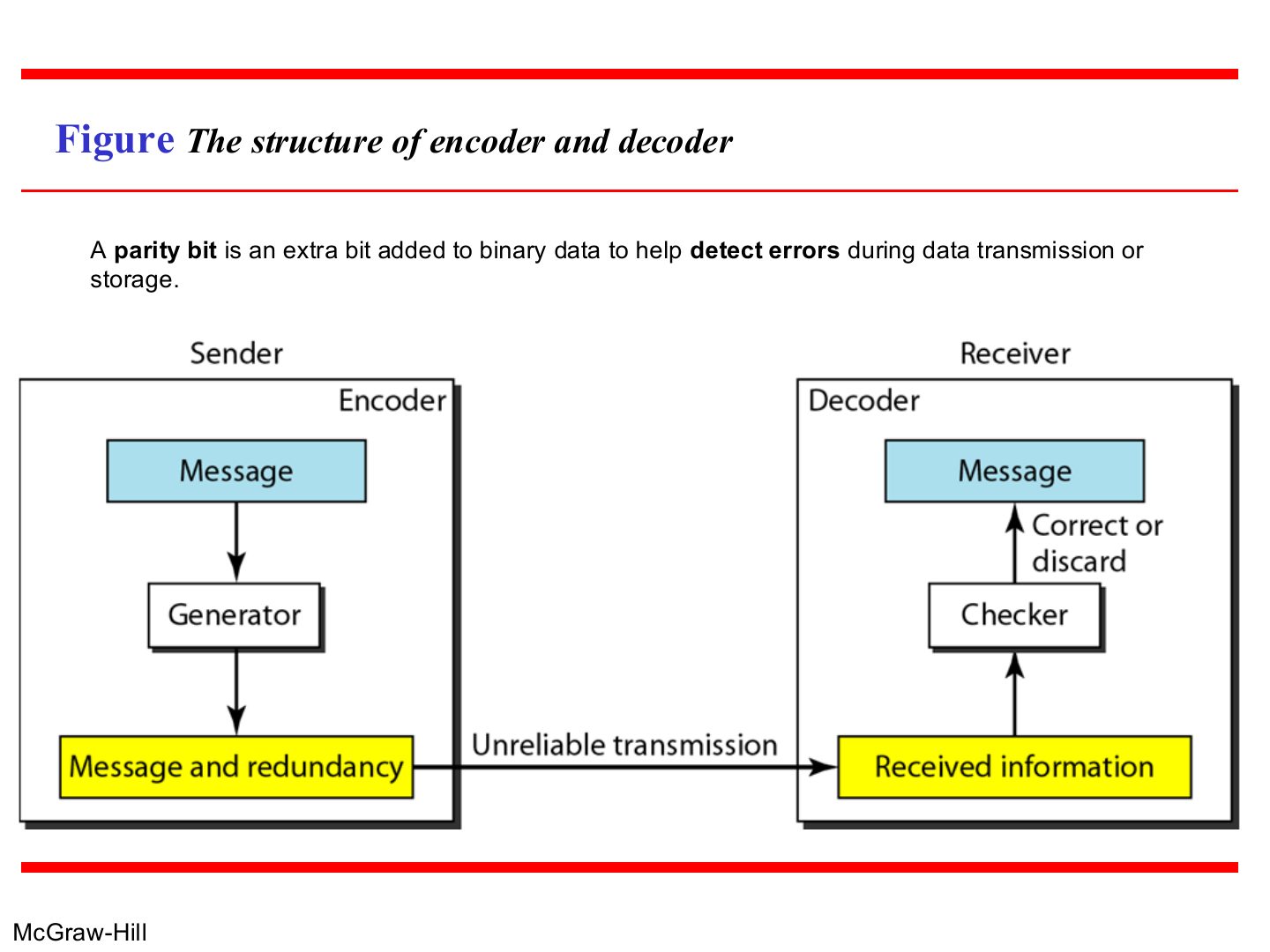
Notes
Sender: a generator adds redundant bits. Receiver: a checker recomputes them and accepts or discards.
Encoder and decoder for simple parity-check code
Note: parity check
Notes
Memory trick Even parity bit = 1 if the data has an ODD number of 1s (so the total becomes even).
Table Simple parity-check code C(5, 4)
Exam angle
With even parity, the dataword 1011 becomes:
- Three 1s → parity 1.
Example 1
Notes
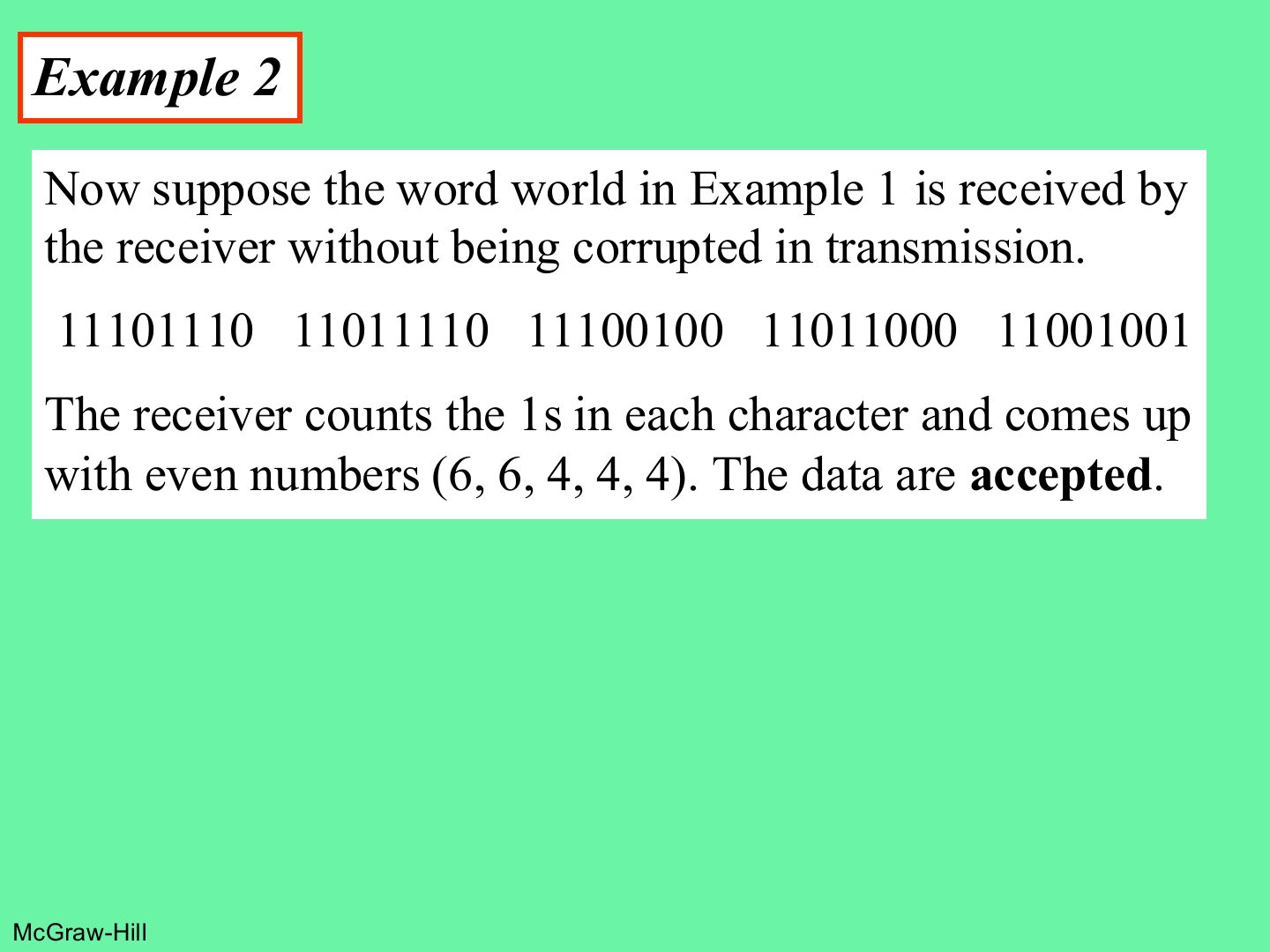
Each 7-bit ASCII character gets one even-parity bit: count the 1s and add 0 or 1 to make the count even.
Exam angle
Q2 · even parity on 7-bit datawords
With even parity, the 7-bit dataword 1111000 becomes:
- Tutorial 4, Q2: four 1s, so parity 0.
With even parity, 1010101 is sent as:
- Tutorial 4, Q2: four 1s, parity 0.
Example 2
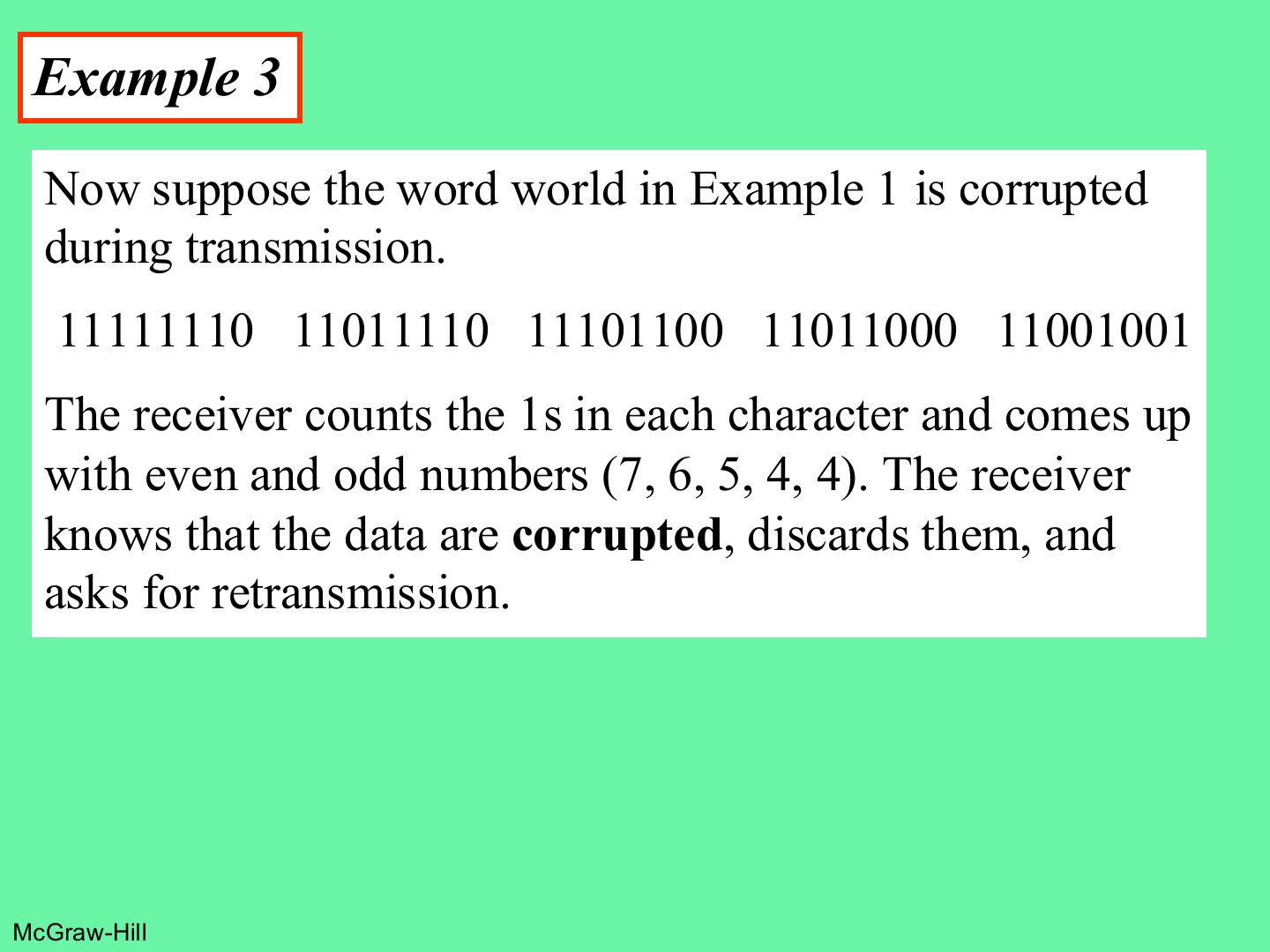
Example 3
Exam angle
Q2b · which received codewords are valid
With even parity, the receiver gets 10101010, 11110001 and 00000001. Which are valid, and can it correct the bad ones?
Compare with the model answer
10101010 has four 1s → valid. 11110001 has five 1s → invalid. 00000001 has one 1 → invalid. Simple parity only detects; it can’t tell which bit flipped, so the receiver discards and asks for retransmission.
Note: what simple parity can detect
Notes
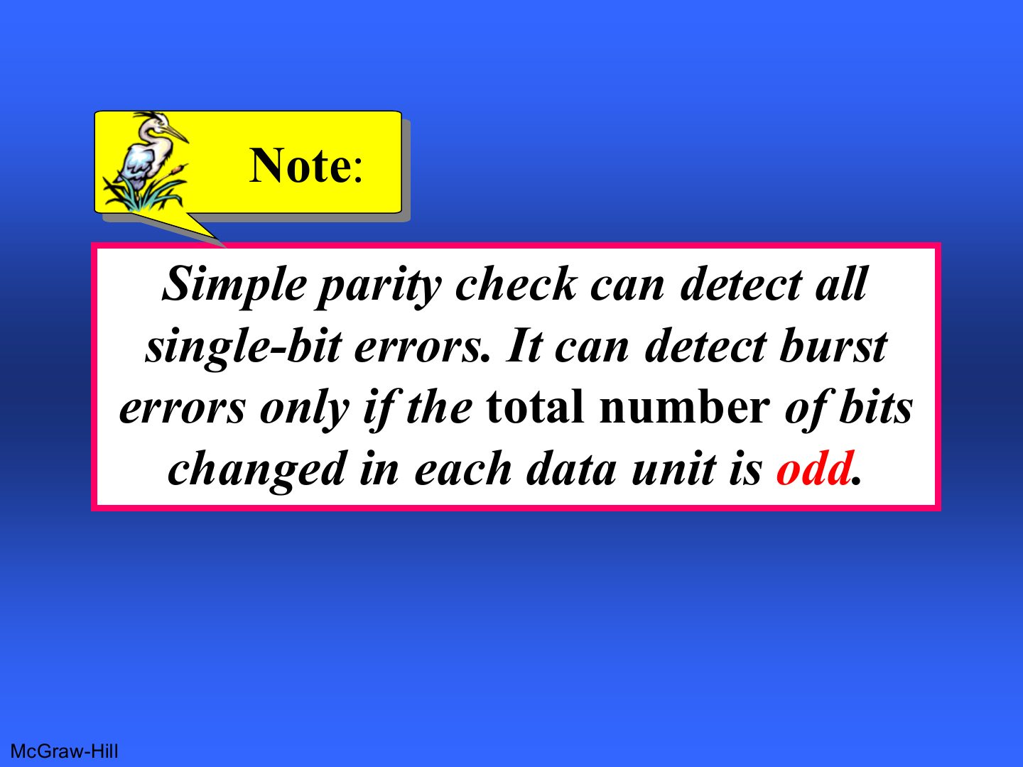
Trap Two flipped bits keep the parity the same, so simple parity misses every even number of errors.
Exam angle
Simple parity check can detect all burst errors.
- Only when an odd number of bits changed.
Simple even parity will NOT detect an error when:
Note: two-dimensional parity
Notes
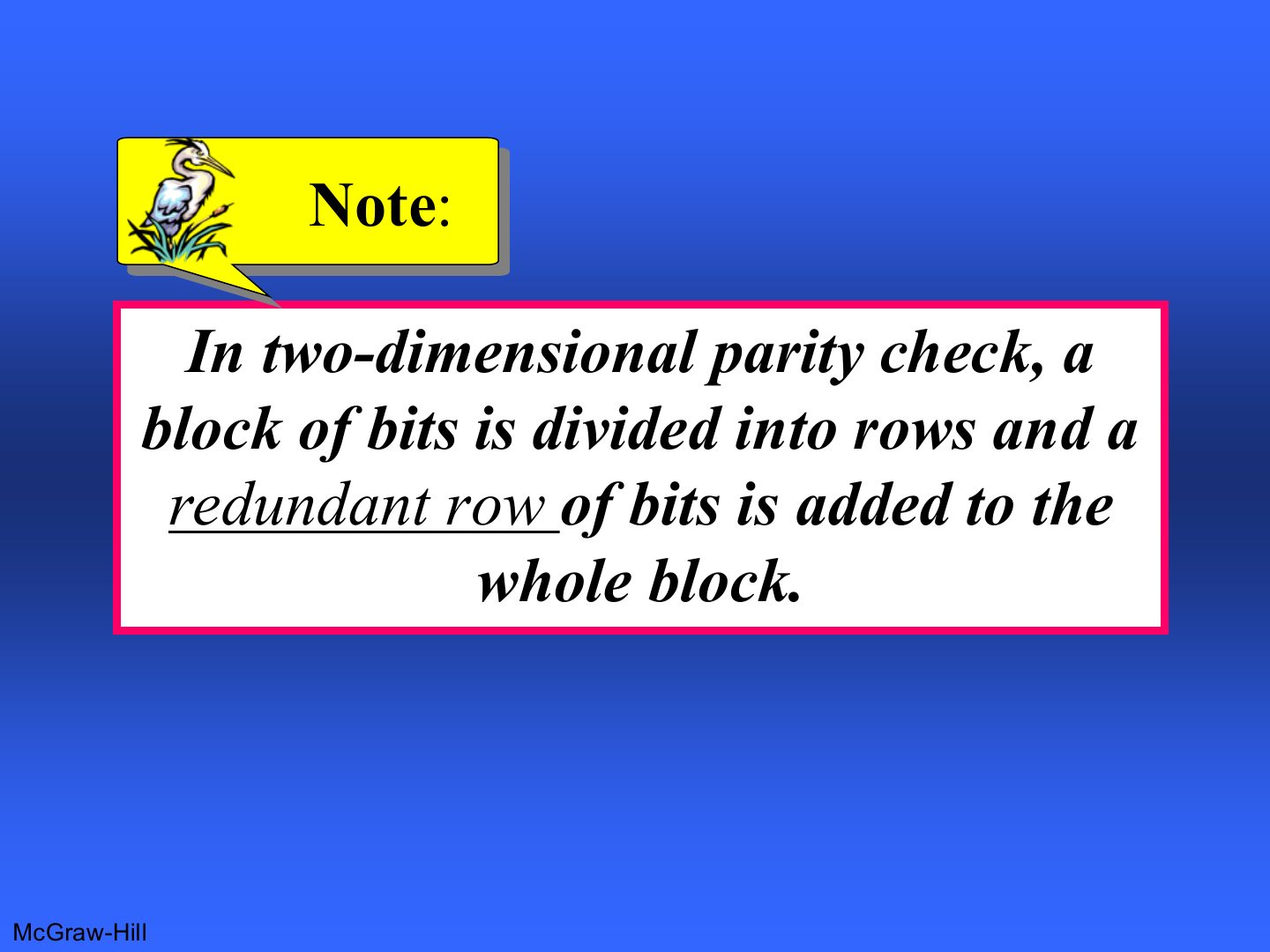
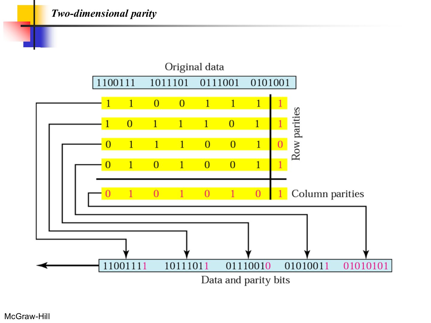
2D parity: arrange the data in rows; add a parity bit to each row AND a parity row for the columns.
Two-dimensional parity
Notes
Row parities catch which row; column parities catch which column. One bad bit = the crossing point, so it can be corrected.
Exam angle
Q1 · 2D parity for 1010, 0111, 1100, 1001
Q8 · 2D parity with a burst error
Compute the 2D even parity for the datawords 1010, 0111, 1100, 1001.
Compare with the model answer
Row parities: 1010→0, 0111→1, 1100→0, 1001→0. Column parities: 1, 0, 0, 0, and the parity of the parity column is 1. Block sent: 1010|0, 0111|1, 1100|0, 1001|0, 1000|1.
Two-dimensional parity: what it detects
Notes
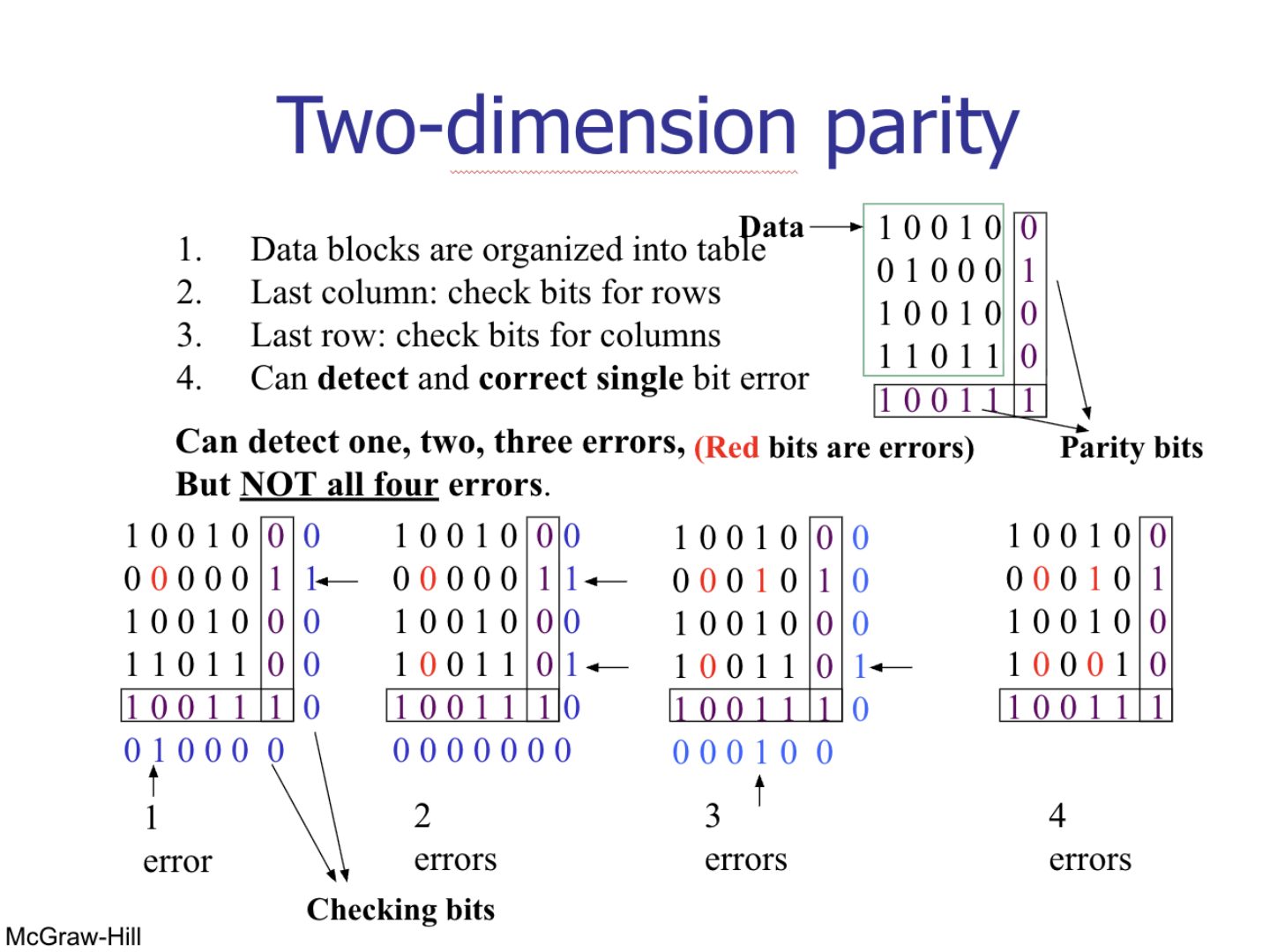
It misses 4 errors that sit at the corners of a rectangle: every row and column still has even parity.
Exam angle
Two-dimensional parity can correct a single-bit error.
- The bad row and bad column cross at the bit.
Which error pattern can two-dimensional parity miss?
CRC generator and checker
Notes
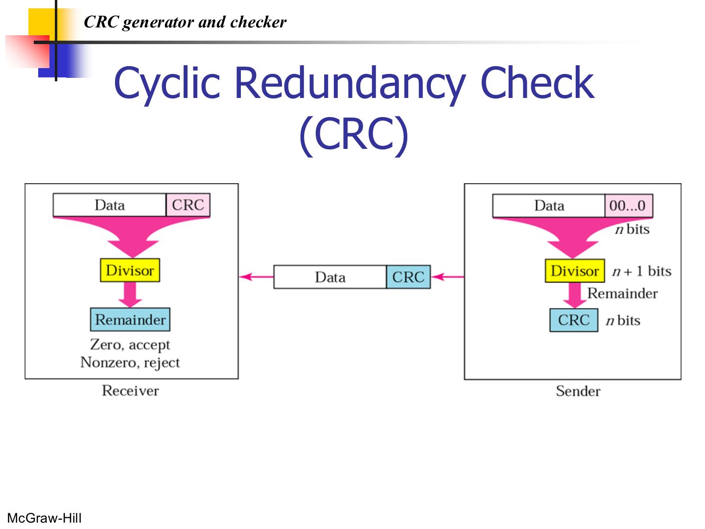
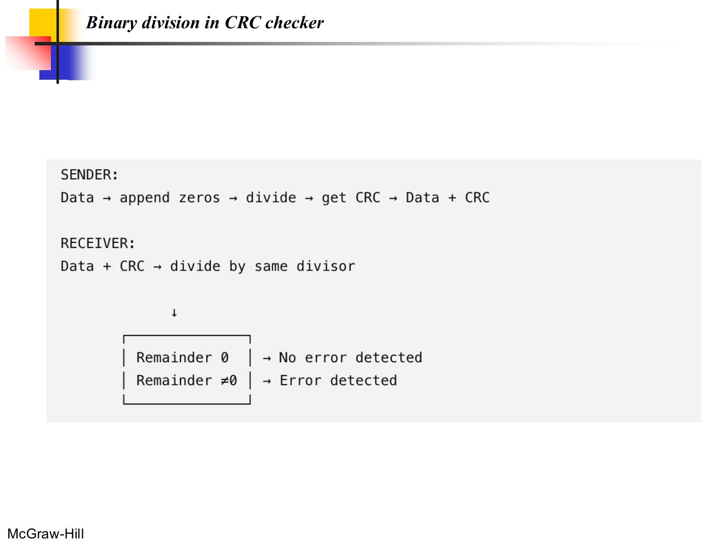
Sender: append n zeros (n = divisor length - 1), divide, the remainder is the CRC. Send data + CRC.
Receiver: divide data + CRC by the same divisor. Remainder 0 → accept; otherwise reject.
Note: the generator
A polynomial to represent a binary word
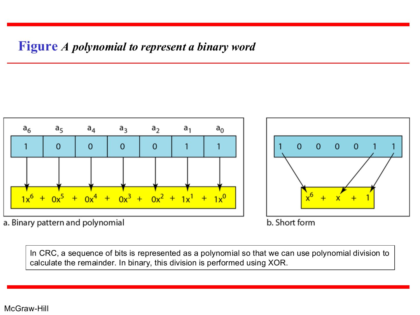
Notes
Each 1 bit is a power of x: 1000011 = x⁶ + x + 1.
Division uses XOR, with no carries.
Memory trick Polynomial → bits: write a 1 for every power present, from the highest down to x⁰. x³ + x + 1 = 1011.
Exam angle
The generator x³ + x + 1 in binary is:
1000011 as a polynomial is:
Division in CRC encoder
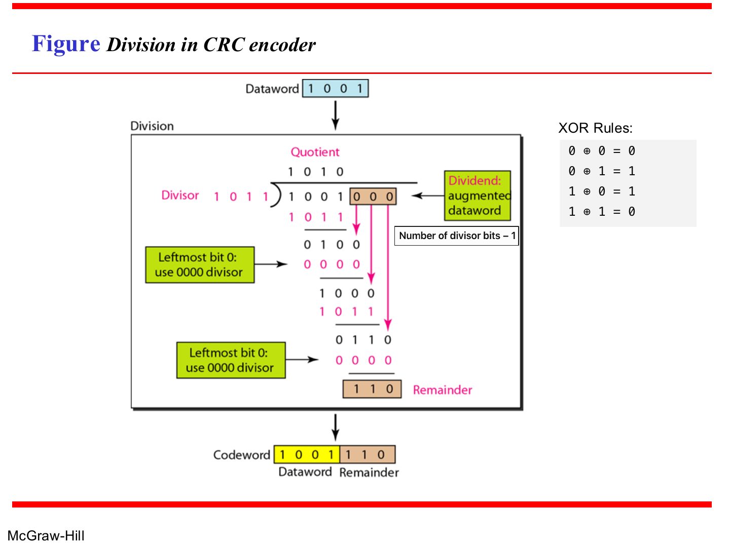
Notes
Dataword 1001 + 000 ÷ 1011 → remainder 110 → codeword 1001110.
When the leftmost bit of the current remainder is 0, divide by 0000 instead (just bring the next bit down).
Exam angle
Q5 · CRC of 11010011 with 1011
Q7 · CRC of 101110 with x³ + x + 1
With generator 1011, the CRC for dataword 11010011 is:
- Tutorial 4, Q5: transmitted codeword 11010011011.
With generator x³ + x + 1, the frame sent for data 101110 is:
- Tutorial 4, Q7: the remainder is 110.
With generator 1011, the CRC for dataword 1101 is:
- Tutorial 4, Q10b: frame 1101001.
Division in the CRC decoder for two cases
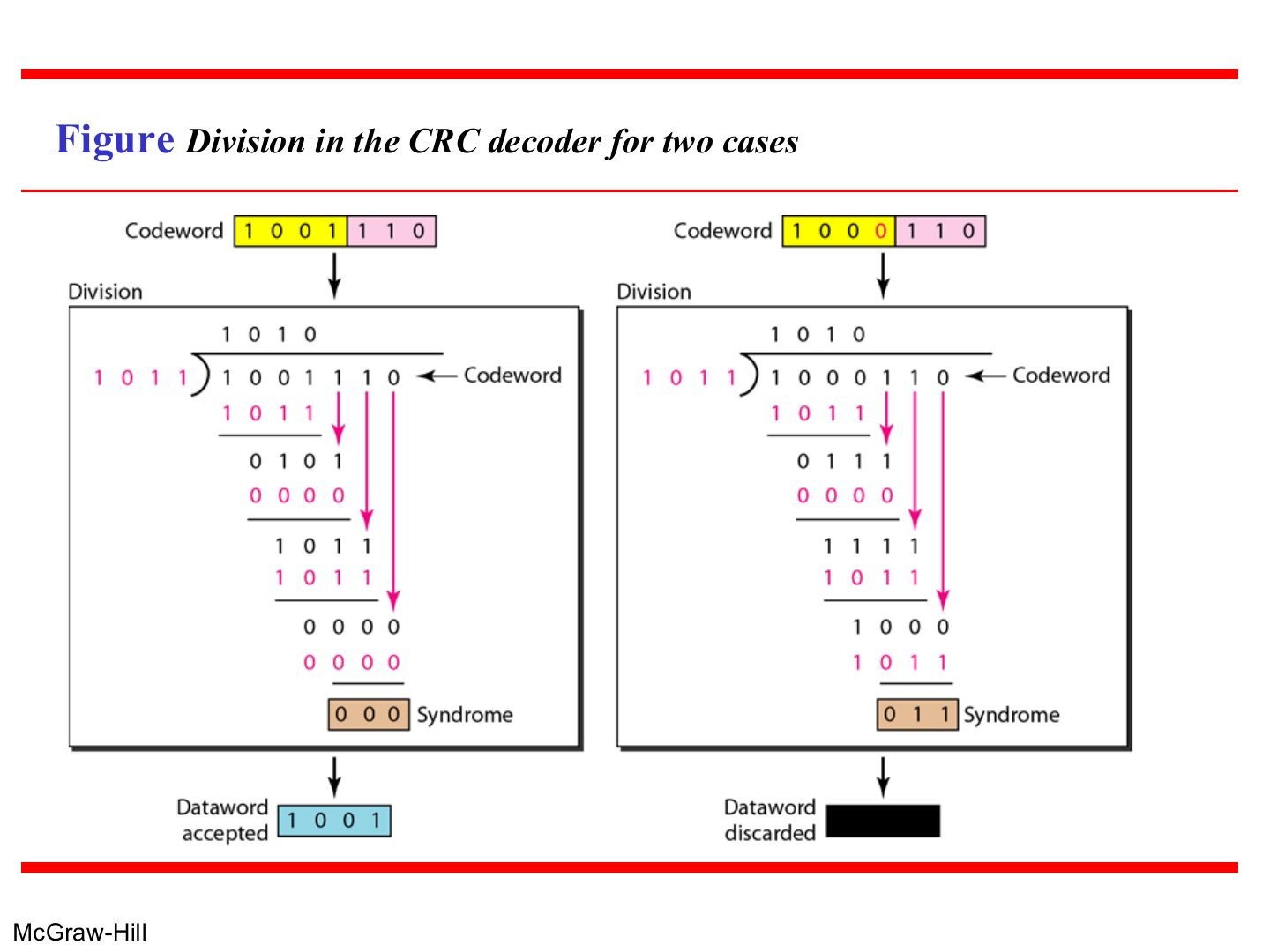
Notes
Remainder (syndrome) 000 → accept. Anything else → discard.
Exam angle
Q5b · is 11010011101 accepted
Q7b–c · checking received frames
Generator 1011. The receiver gets 11010011101. What happens?
- Tutorial 4, Q5b.
Generator x³ + x + 1: the received frame 101110101 is accepted.
- Tutorial 4, Q7b: the remainder is 011, so it is rejected.
Binary division in CRC checker
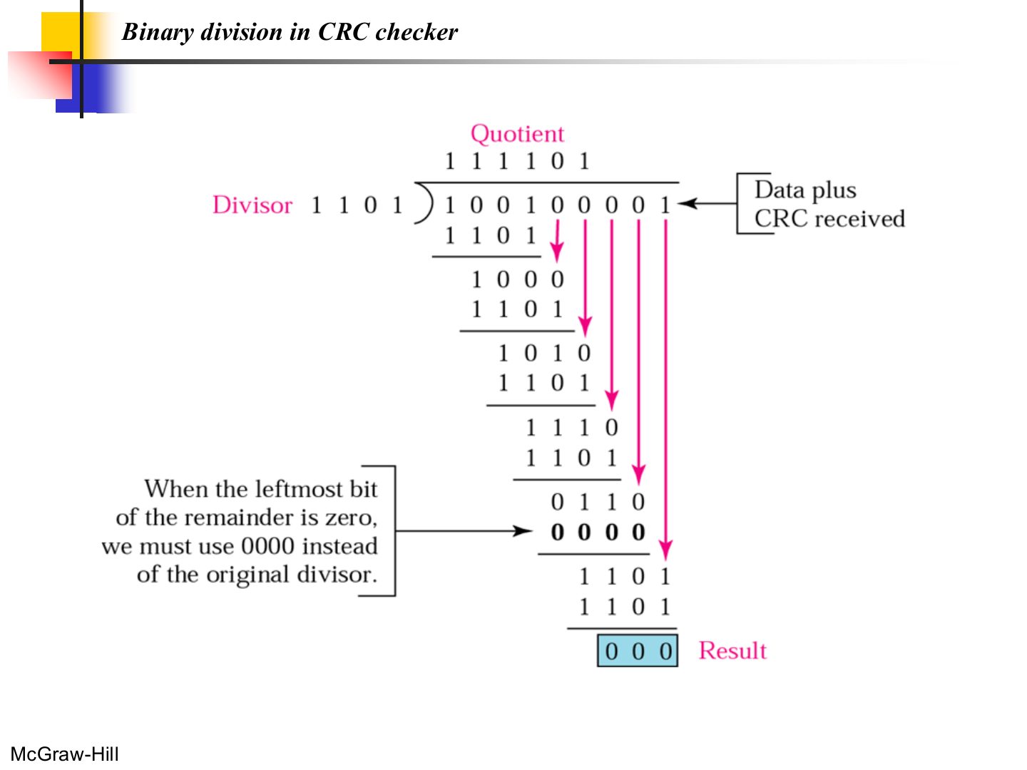
Notes
A zero remainder means no error detected.
CRC summary
Notes
Trap Generator 1011 has 4 bits → append 3 zeros and the CRC is 3 bits.
Standard polynomials
Notes
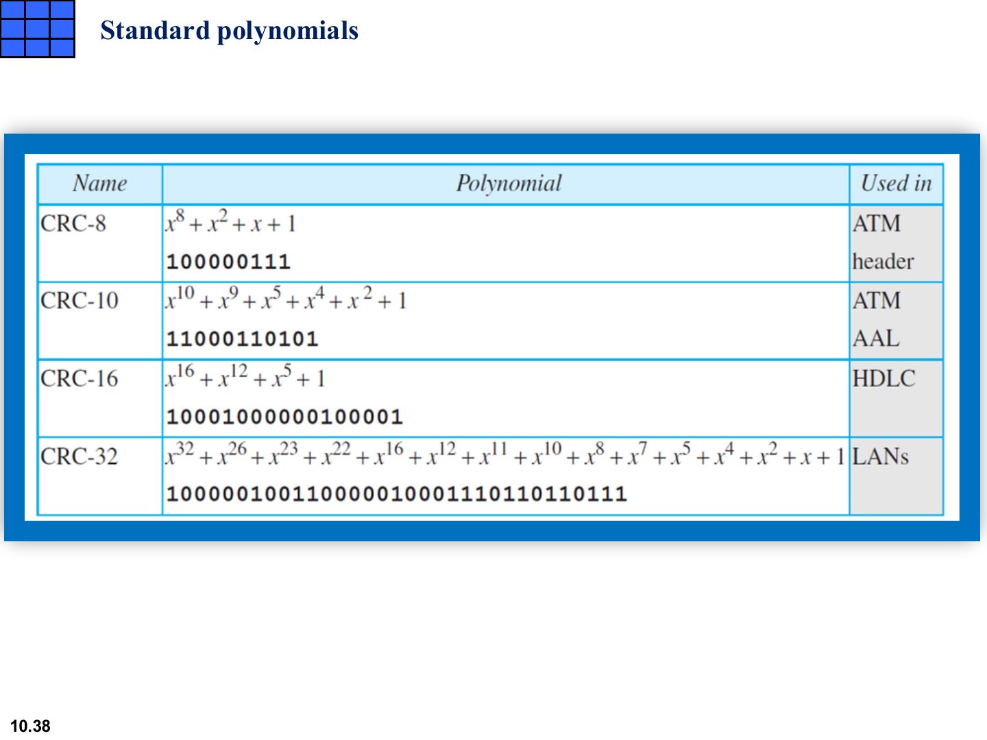
CRC-32 is the one used in LANs (Ethernet’s FCS).
Seen again Ch 4, slide 4: The Ethernet frame’s CRC field
Advantages of Cyclic Codes
Notes
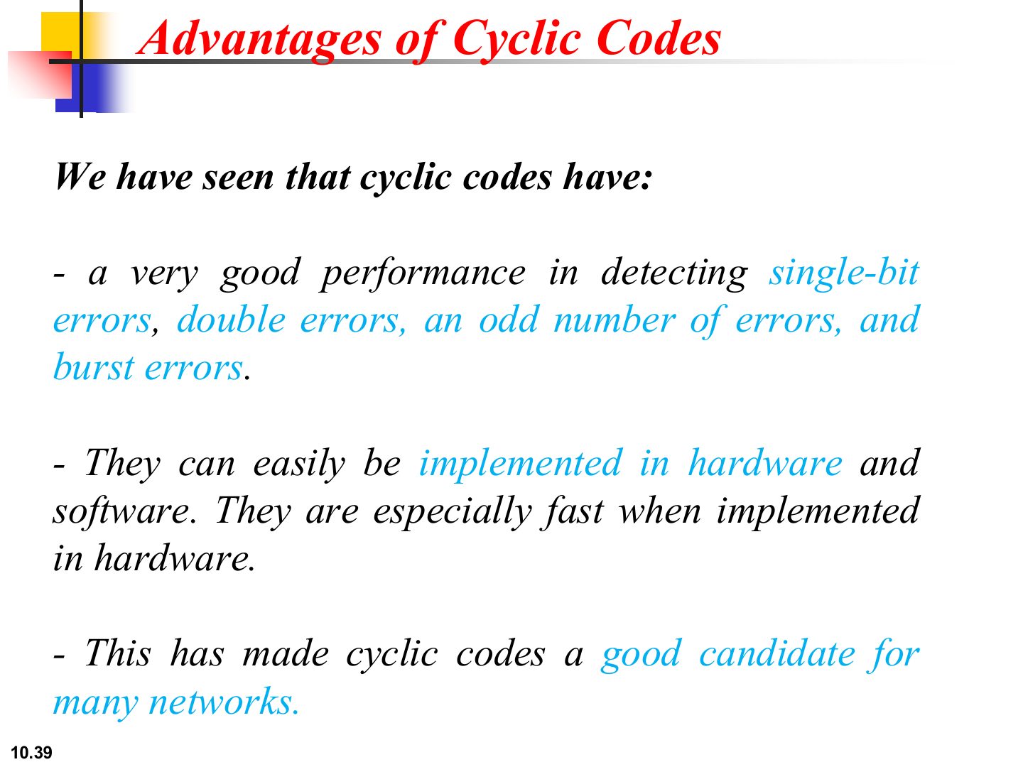
CRC catches single, double, odd-count and burst errors, and is fast in hardware.
Example
Notes
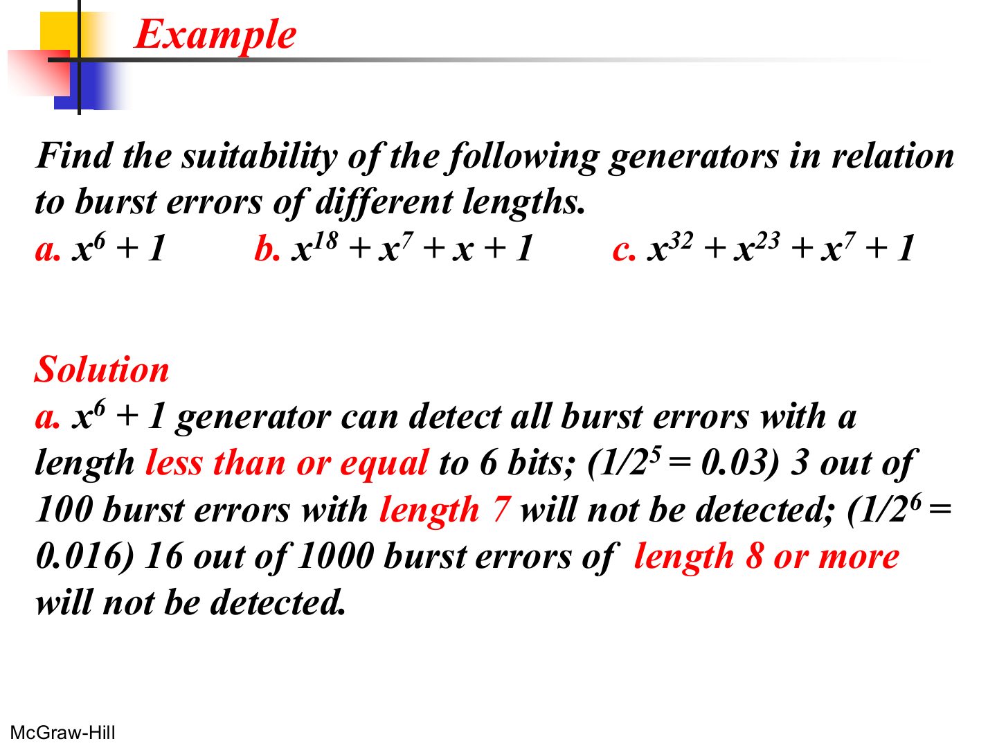
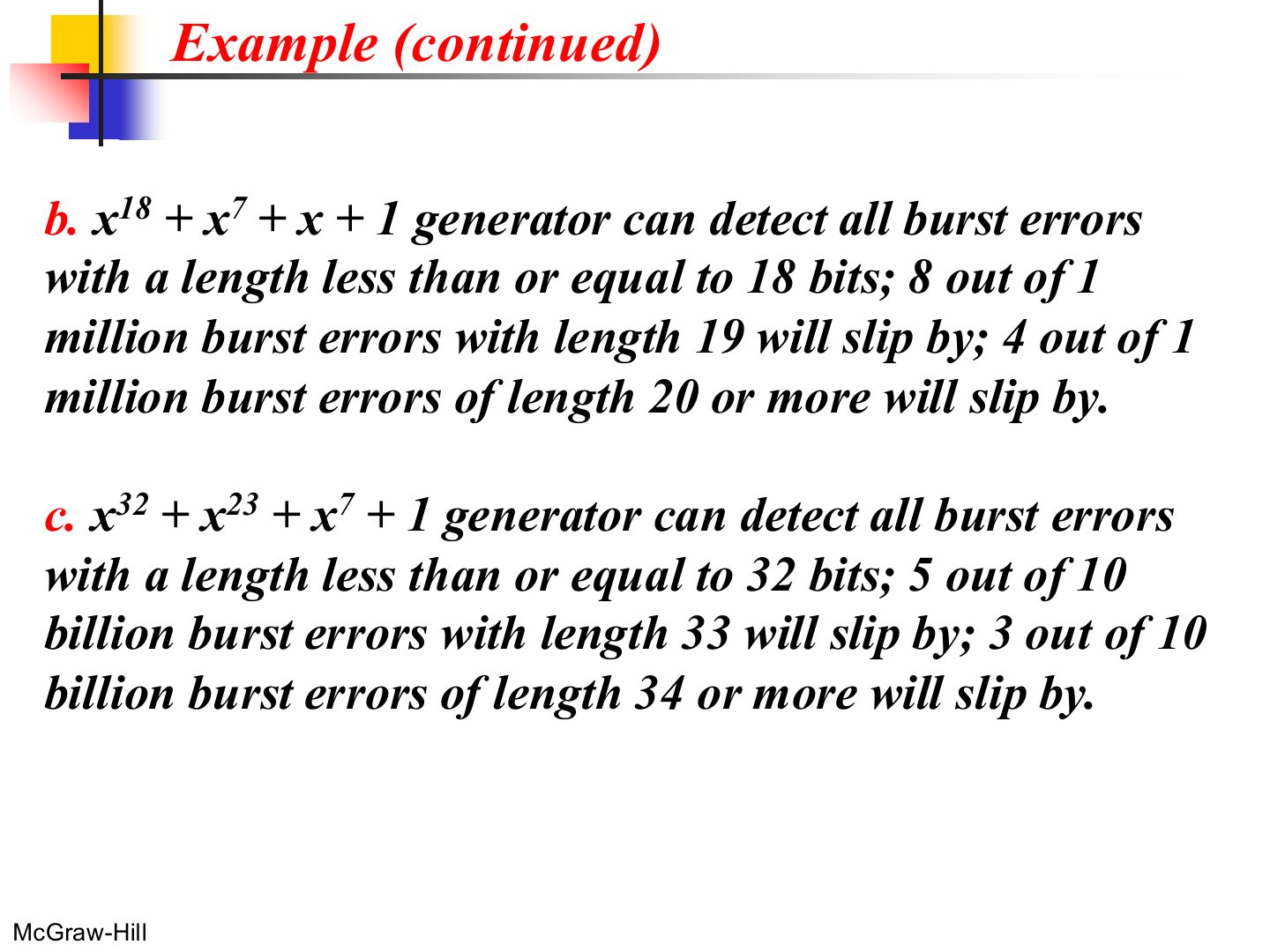
Length r + 1 slips by with probability 1/2^(r-1); longer ones with 1/2^r.
Memory trick Degree = highest power. x⁶ + 1 → 6 → all bursts up to 6 bits.
Exam angle
The generator x¹⁸ + x⁷ + x + 1 detects all burst errors of length up to:
Example (continued)
Notes
Higher degree → longer bursts caught → that’s why LANs use CRC-32.
Checksum
Notes
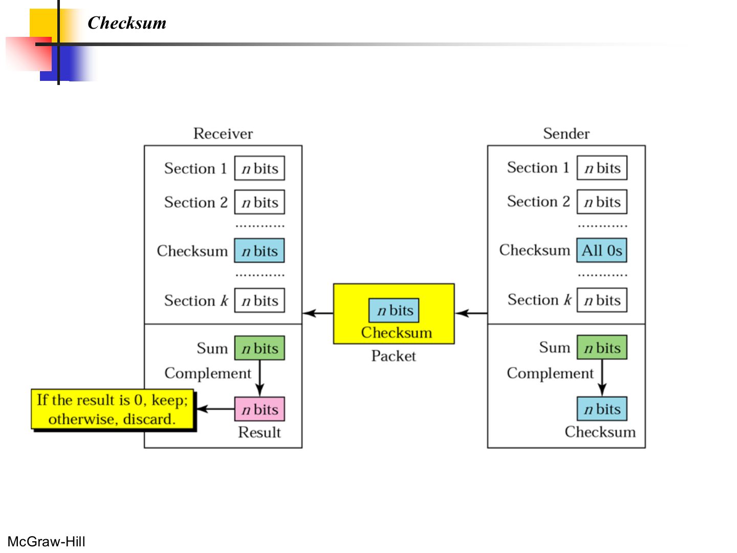
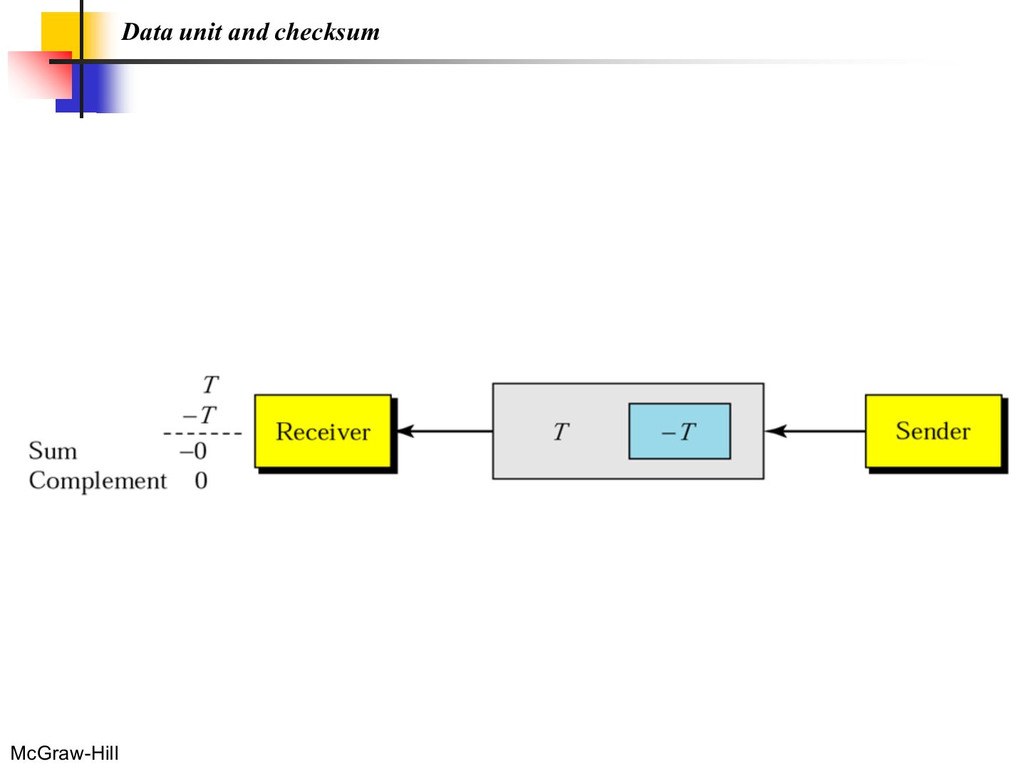
Checksum: add all words (one’s complement), complement the sum, send it. The receiver adds everything; complemented result 0 = OK.
Seen again Ch 9, slide 20: The UDP and TCP checksum
Data unit and checksum
Checksum: sender site
Notes
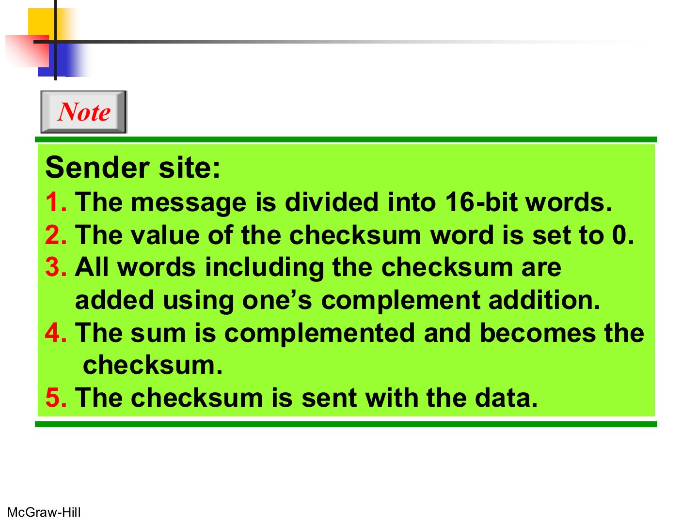
Steps: split into 16-bit words, checksum field = 0, add with one’s complement, complement → checksum.
Memory trick One’s complement addition: any carry out of the top bit wraps around and is added back at the bottom.
Checksum: receiver site
Notes
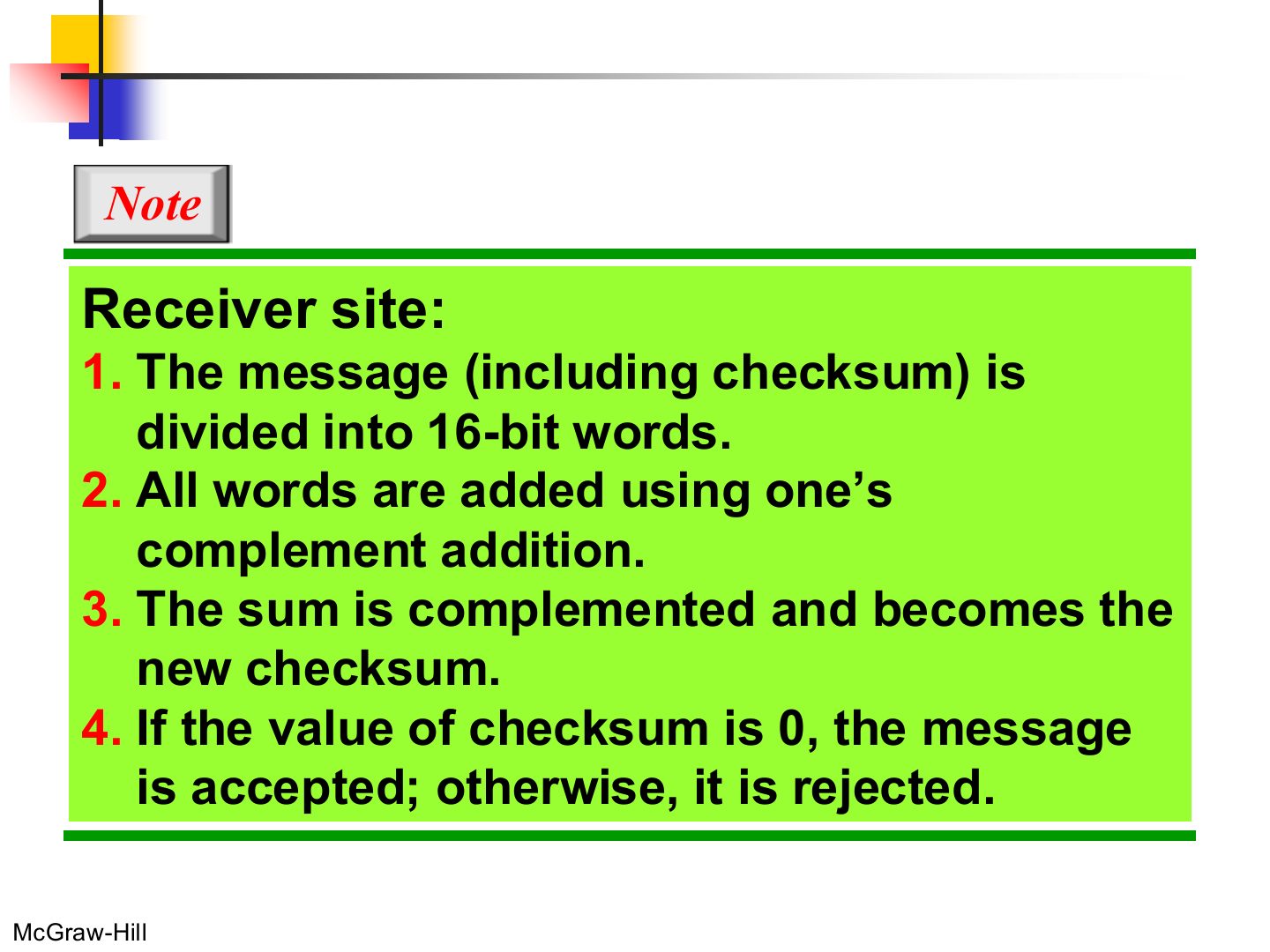
Receiver: add all words INCLUDING the checksum, complement. 0 → accept, anything else → reject.
Example 7
Notes
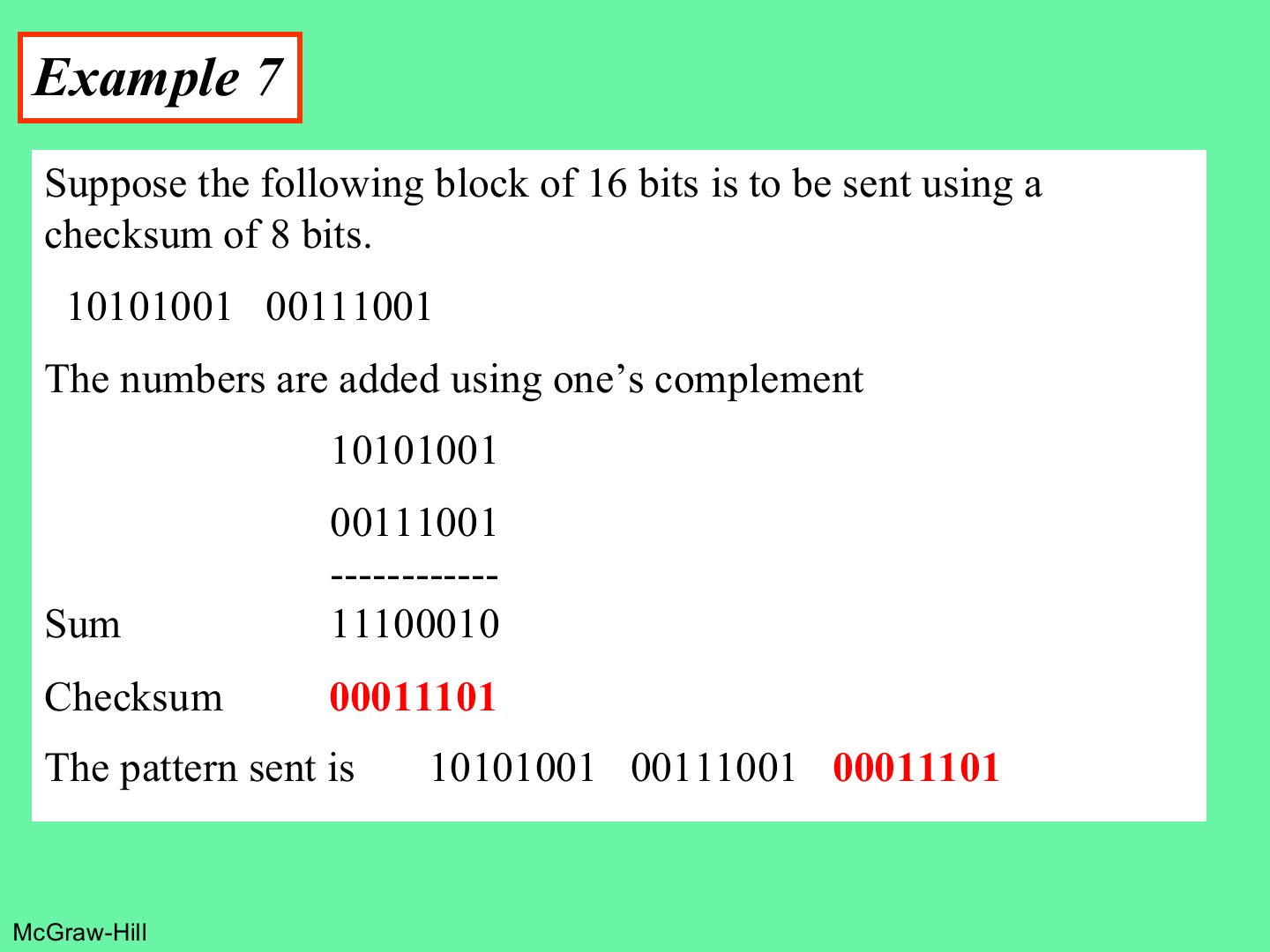
Complement = flip every bit.
Exam angle
Q9 · 8-bit checksum of four words
Q3 · 16-bit checksum
The 8-bit checksum of 10101010, 01010101, 11110000 and 00001111 is:
- Tutorial 4, Q9: the sum is 11111111, so the complement is 00000000.
Sender words 1100110011001100 and 1010101010101010. The 16-bit checksum is:
- Tutorial 4, Q3: the sum with the carry wrapped is 0111011101110111; its complement is the checksum.
Example 8
Exam angle
Q3b · verifying a received checksum
In Tutorial 4 Q3, the receiver gets checksum 0110010101100101 for the two words. The packet is error-free.
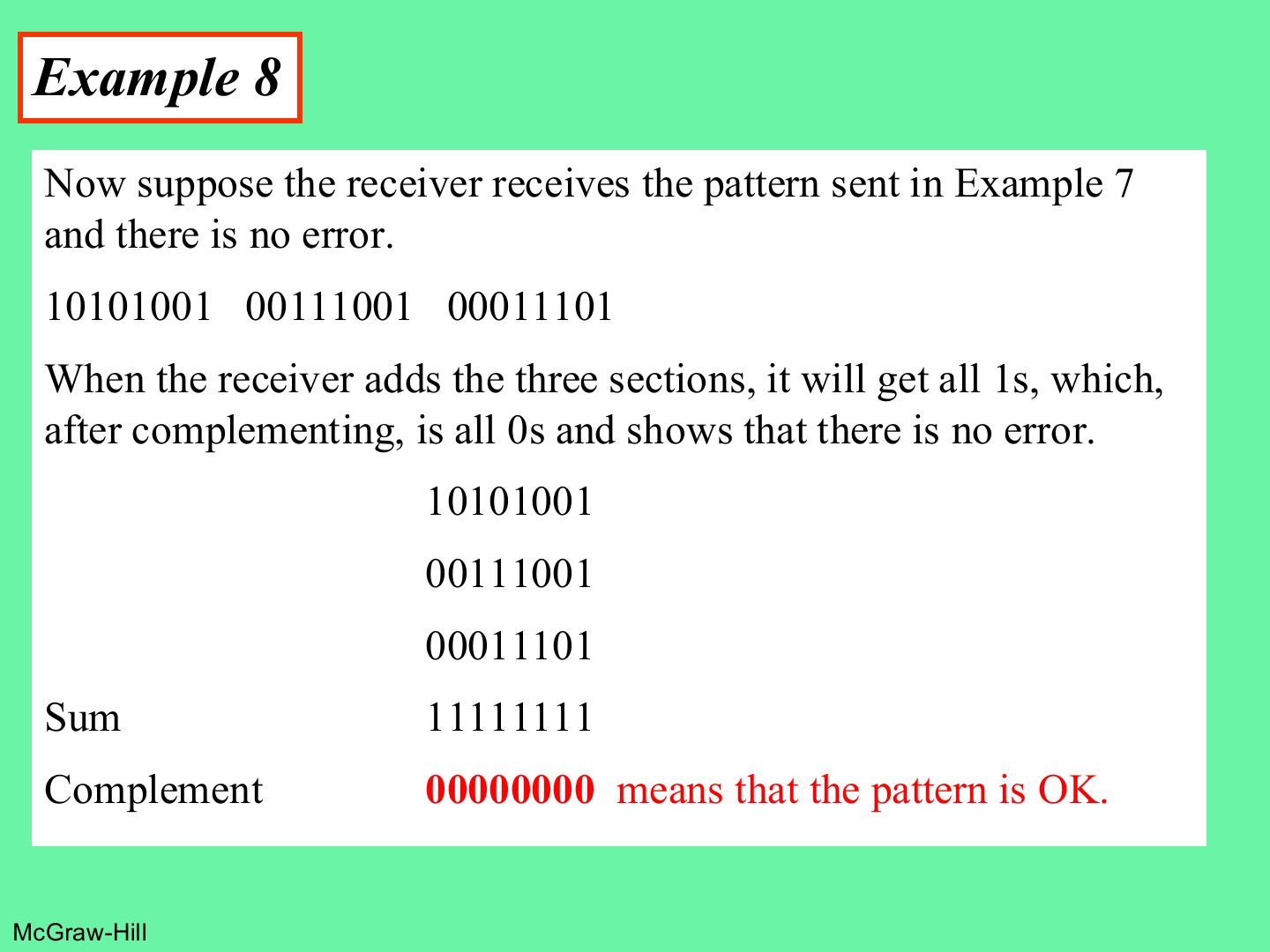
- The correct checksum is 1000100010001000; with the received one the complemented sum is not 0, so an error is detected.
Example 9
Notes
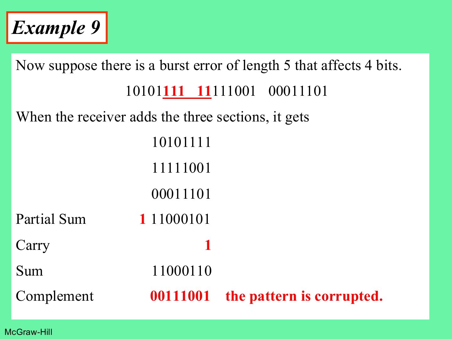
Nonzero after complementing → corrupted.
Error correction
Notes
Two ways to fix errors: send it again, or send enough redundancy to fix it on arrival (FEC).
Error correction 1: retransmission
Notes
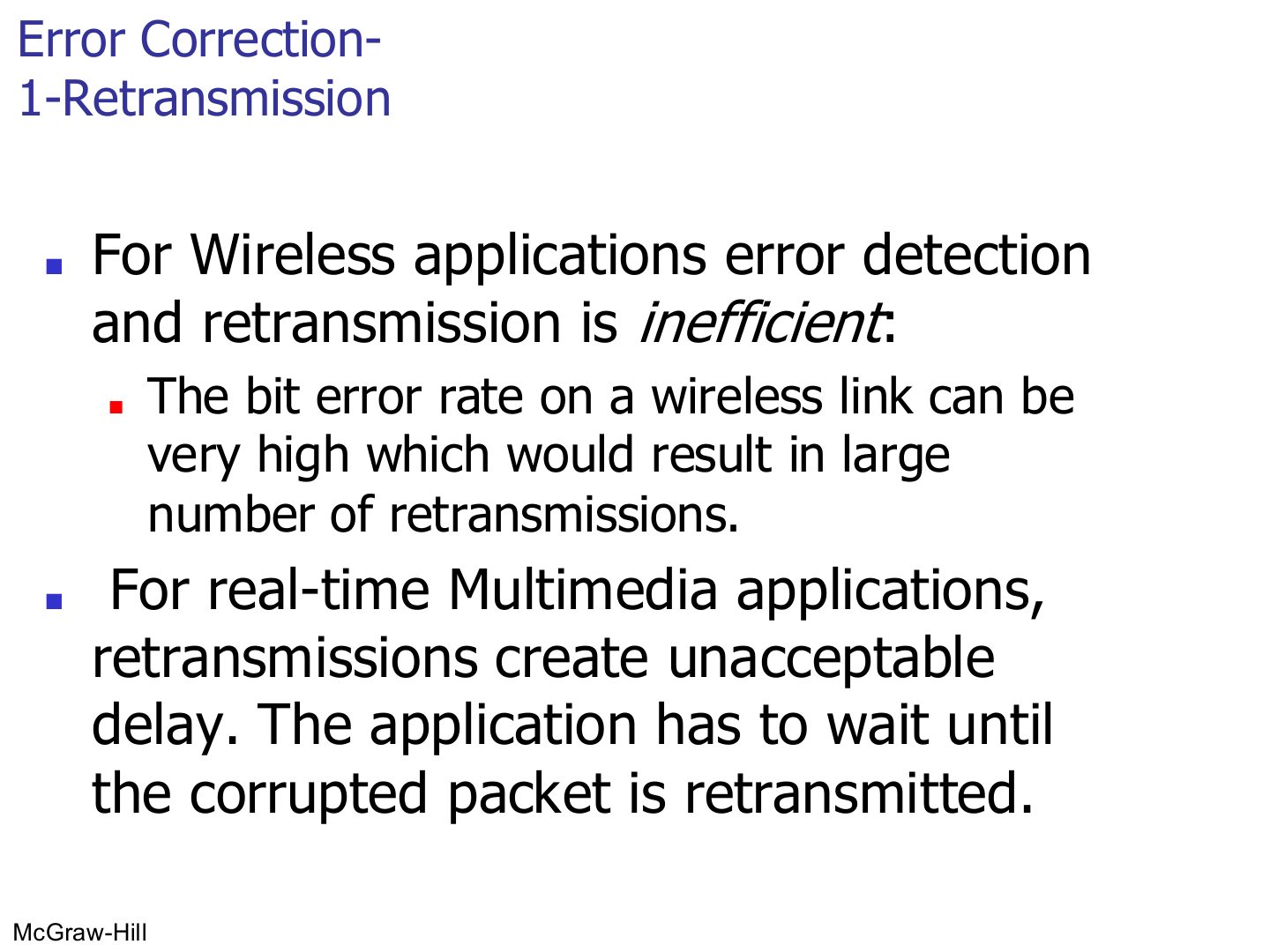
Retransmission is bad for wireless (high bit error rate → too many resends) and for real-time multimedia (waiting = delay).
Exam angle
Retransmission is a poor fit for real-time multimedia because:
Error correction 2: forward error correction (FEC)
Notes
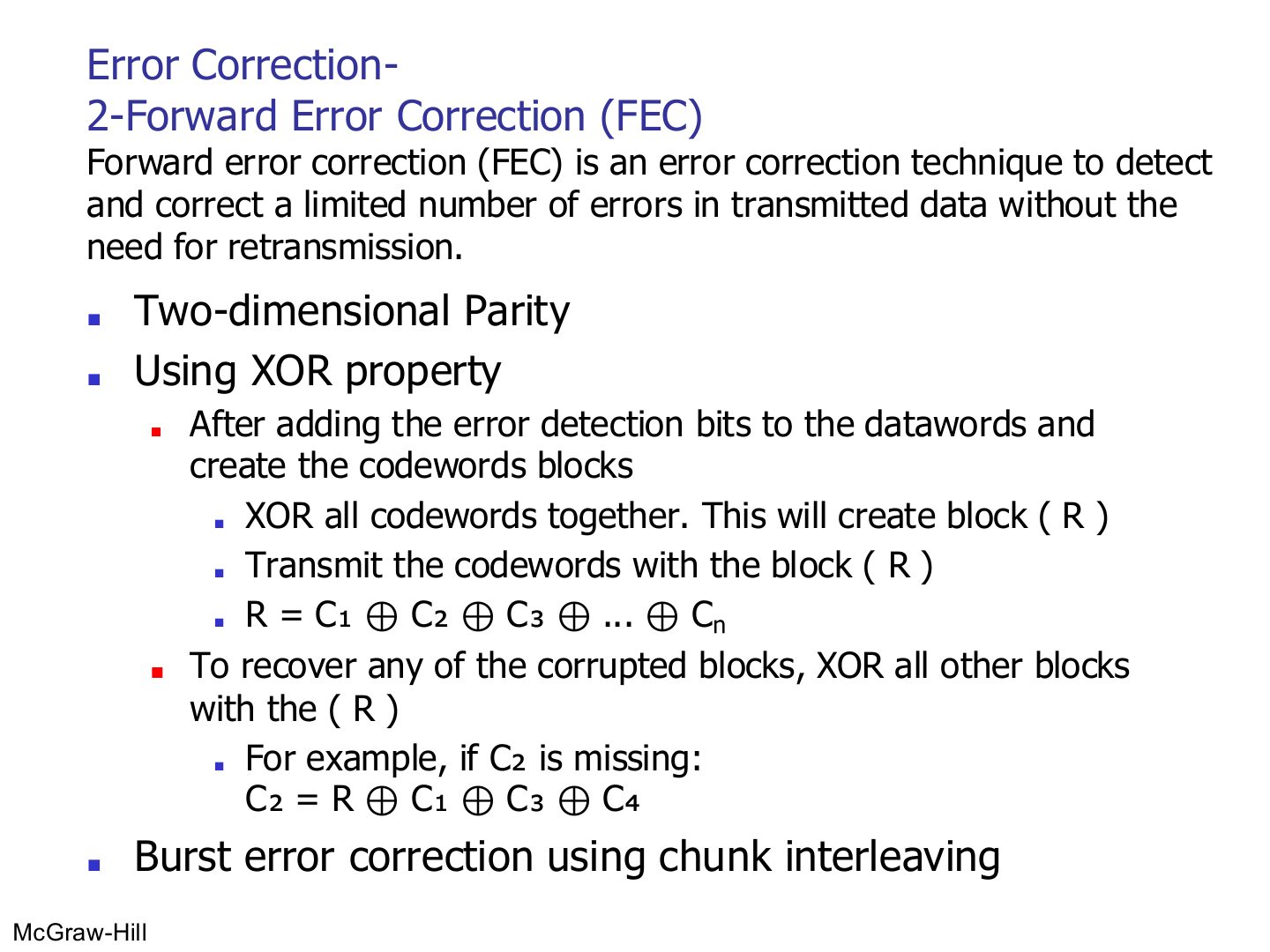
FEC fixes errors at the receiver with no resend.
XOR trick: send R = XOR of all blocks; any ONE lost block = XOR of R with the rest.
Exam angle
Blocks C1..C4 and R = C1 ⊕ C2 ⊕ C3 ⊕ C4 are sent, and C3 is lost. C3 equals:
Forward error correction needs the sender to retransmit corrupted data.
Burst Error Correction Chunk Interleaving
Notes
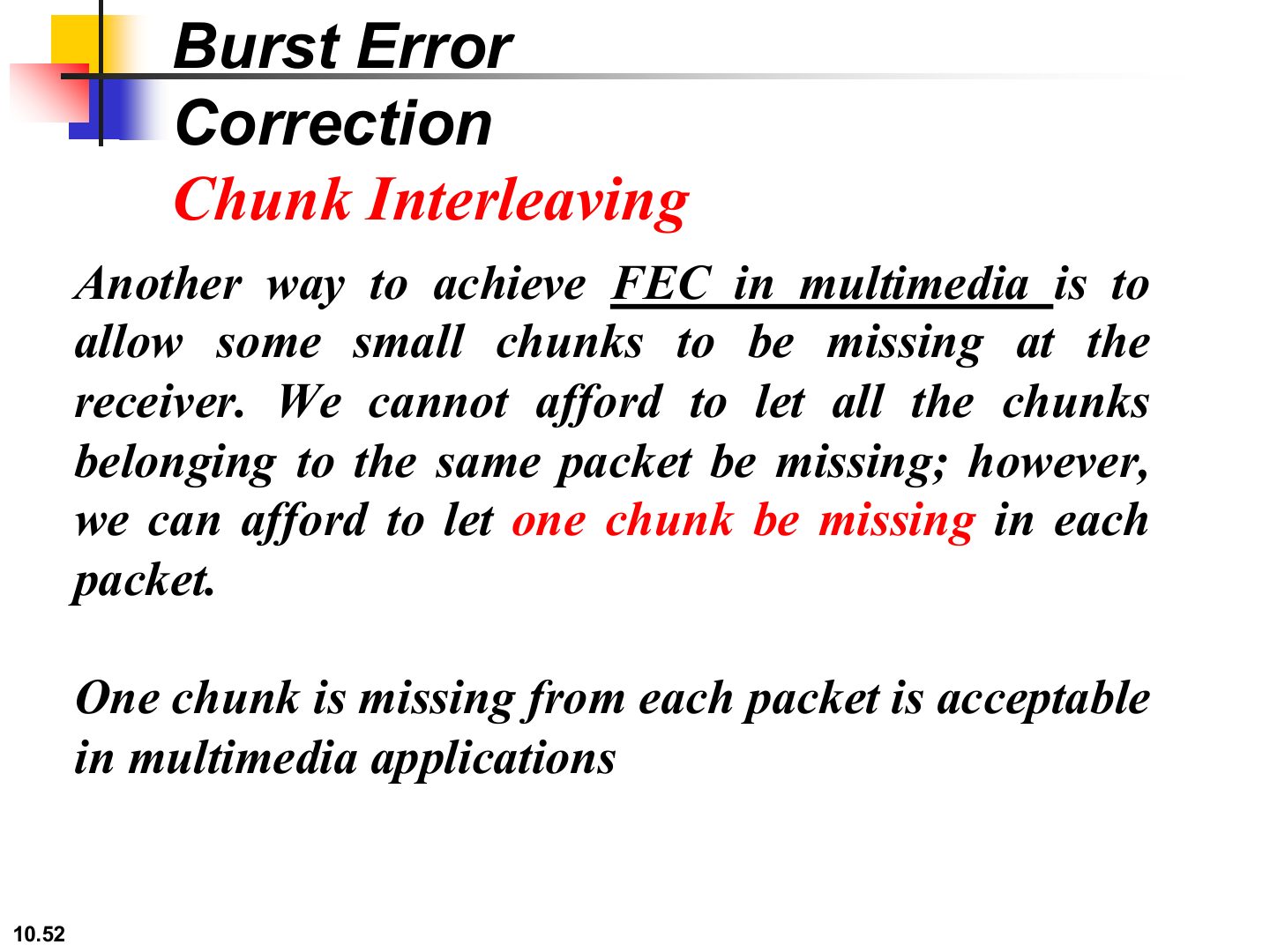
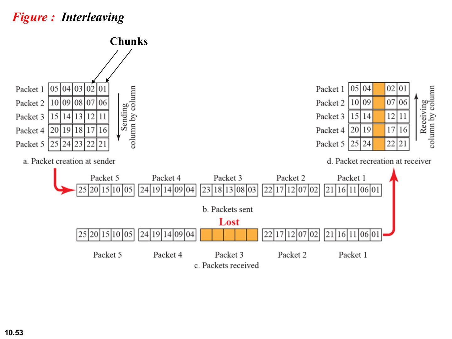
Interleave: spread each packet’s chunks across several transmitted packets. Losing one packet then costs each original packet only one chunk, which multimedia can tolerate.
Interleaving
Notes
The lost packet (orange) removes one chunk from each of the five packets instead of a whole packet.
Exam angle
A video stream loses one whole packet in a burst. How does chunk interleaving keep the video watchable?
Compare with the model answer
Each original packet’s chunks were spread over several transmitted packets (sent column by column). Losing one transmitted packet removes just one small chunk from each original packet, a gap small enough for multimedia to hide, instead of losing an entire packet.