The transmission medium is located above the physical layer.
- Below it, and controlled by it.
Guided media (twisted pair, coaxial, fiber) and unguided media (radio, microwave, infrared): how each one is built, what it is good and bad at, UTP vs. STP and the cable categories, RJ-45 pinouts and when you need a crossover cable. Most questions here are comparisons, so the notes keep pointing at the differences.
Every original slide is shown unchanged. Yellow marks on a slide point to a numbered note: hover or tap a mark to jump to its note, and hover a note to see its marks. Questions tagged Past exam appeared on a real paper; Prediction questions are likely angles, not confirmed. Pick an answer to each question: a wrong pick tells you why it is wrong, so you can try again.
Guided (wired): twisted pair, coax, fiber. Unguided (wireless): radio, microwave, infrared.
Know one advantage and one disadvantage of each, plus the frequency ranges of the three wireless types.
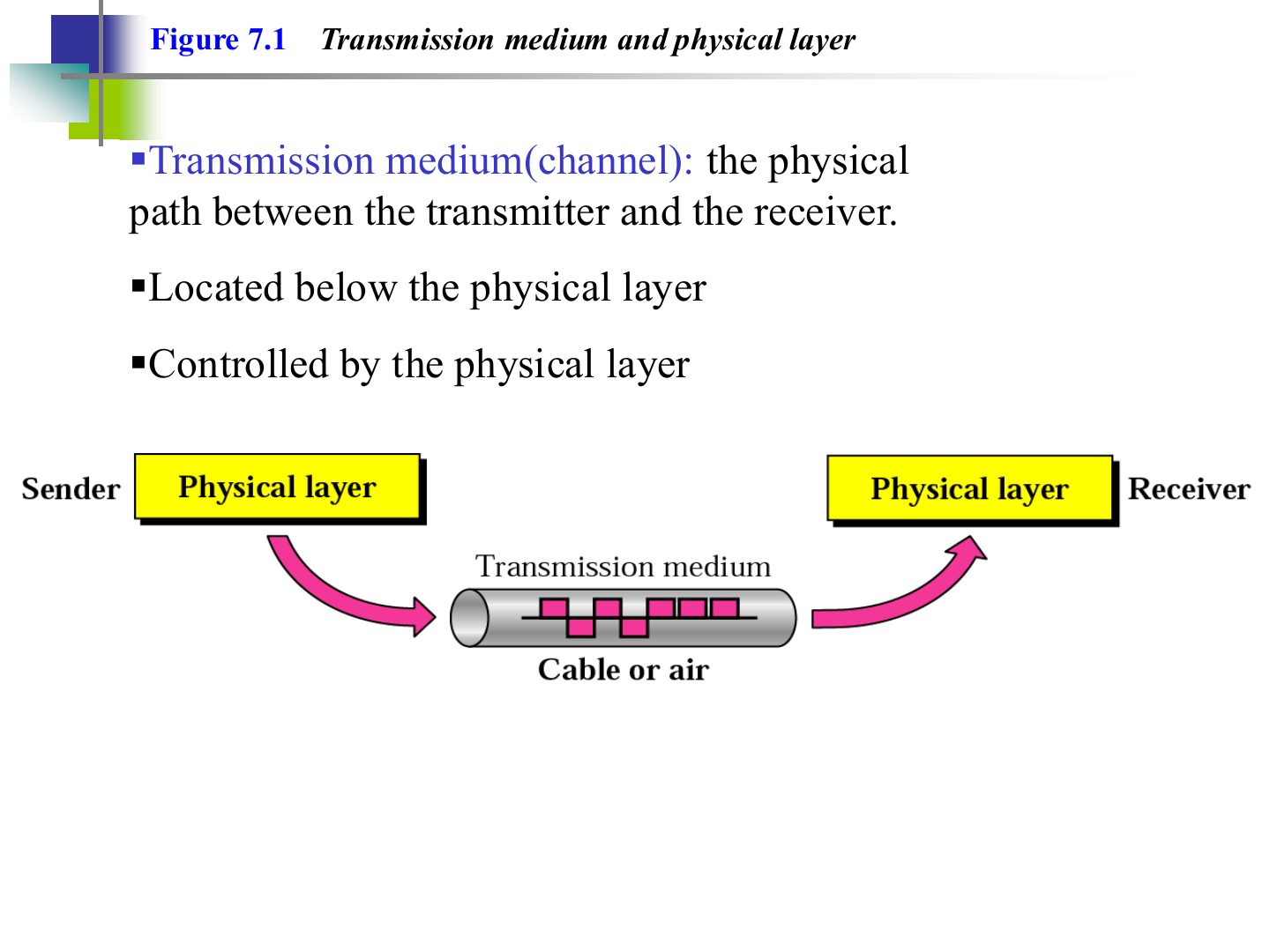
Seen again Ch 1 Part 1, slide 3: The medium as a component of data communication
The transmission medium is located above the physical layer.
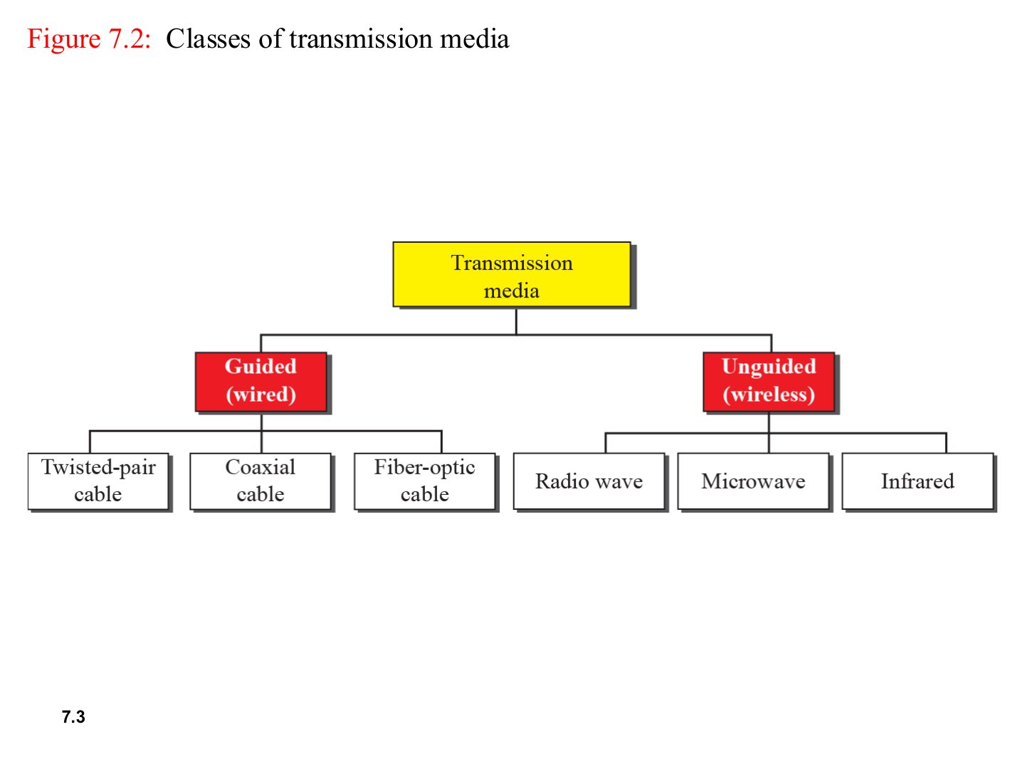
Memory trick Guided = the signal is GUIDED along a physical path. Unguided = it just spreads through the air.
Which is an unguided medium?
Fiber-optic cable is classified as:
Three guided media, from cheapest and slowest to most expensive and fastest.
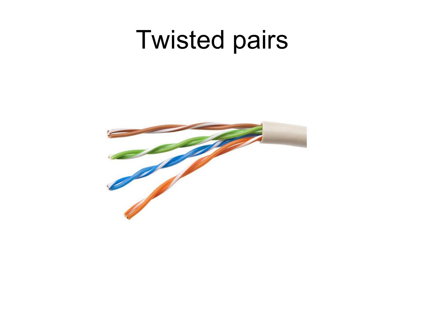
Four pairs, each a different colour, inside one jacket.
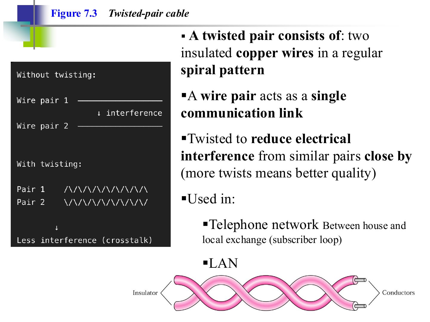
Why are the wires in a twisted pair twisted?
More twists per length gives better quality twisted-pair cable.
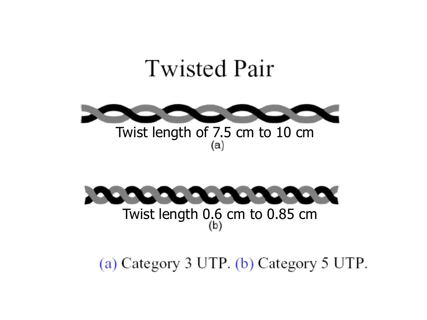
Cat 5 is twisted far more tightly than Cat 3, so it carries higher frequencies with less crosstalk.
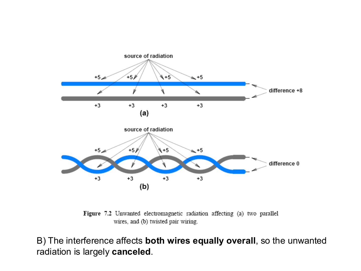
The receiver looks at the DIFFERENCE between the two wires. Twisting makes the noise equal on both, so it subtracts out.
Explain how twisting a pair of wires reduces noise.
In parallel wires one wire is always closer to the noise source and picks up more noise, so a difference remains. Twisting swaps the positions all along the cable, so both wires pick up the same total noise; the receiver uses the difference between them, and the noise cancels.
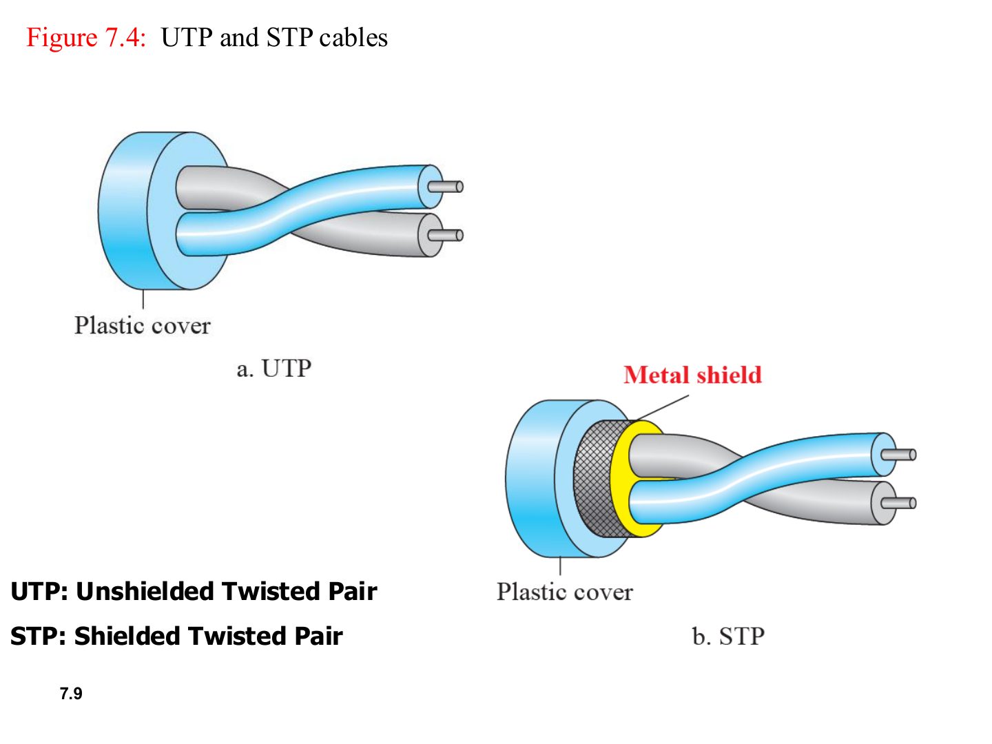
STP adds a metal shield (foil or braid) around the pairs.
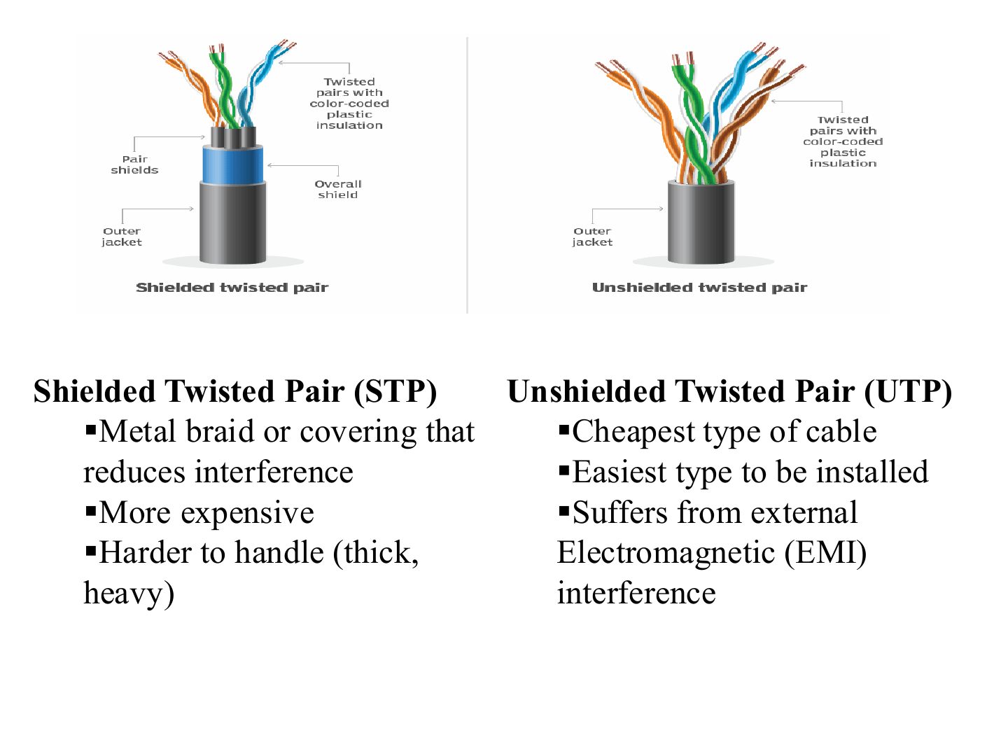
Trap UTP is not “worse” for every case: it is the default in LANs because it is cheap and easy.
Compared with UTP, STP:
A factory floor has heavy motors next to where the network cables will run. UTP or STP, and why?
STP. The motors cause electromagnetic interference (induced noise); the metal shield in STP reduces it. UTP would suffer from the EMI. (Fiber would be immune altogether.)
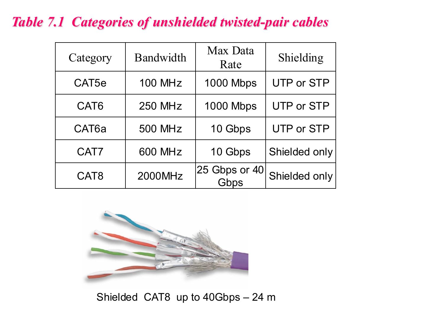
Which is the first category in the table that is shielded only?
CAT6a supports a maximum data rate of:
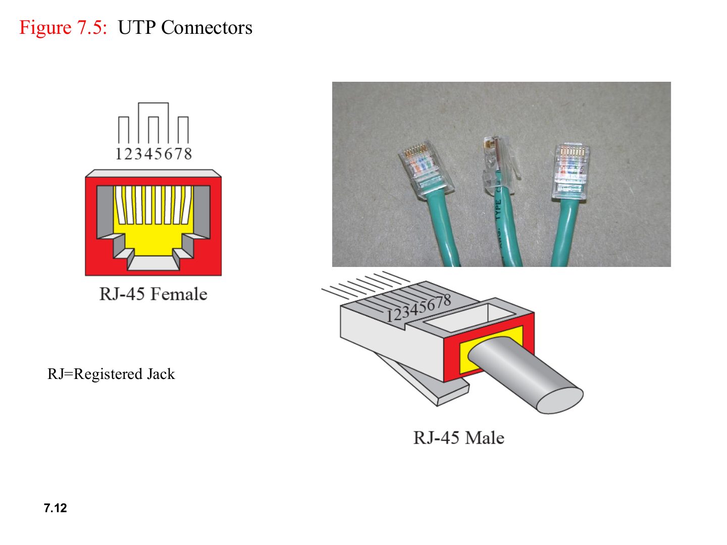
RJ-45 (Registered Jack) is the 8-pin connector of twisted-pair Ethernet.
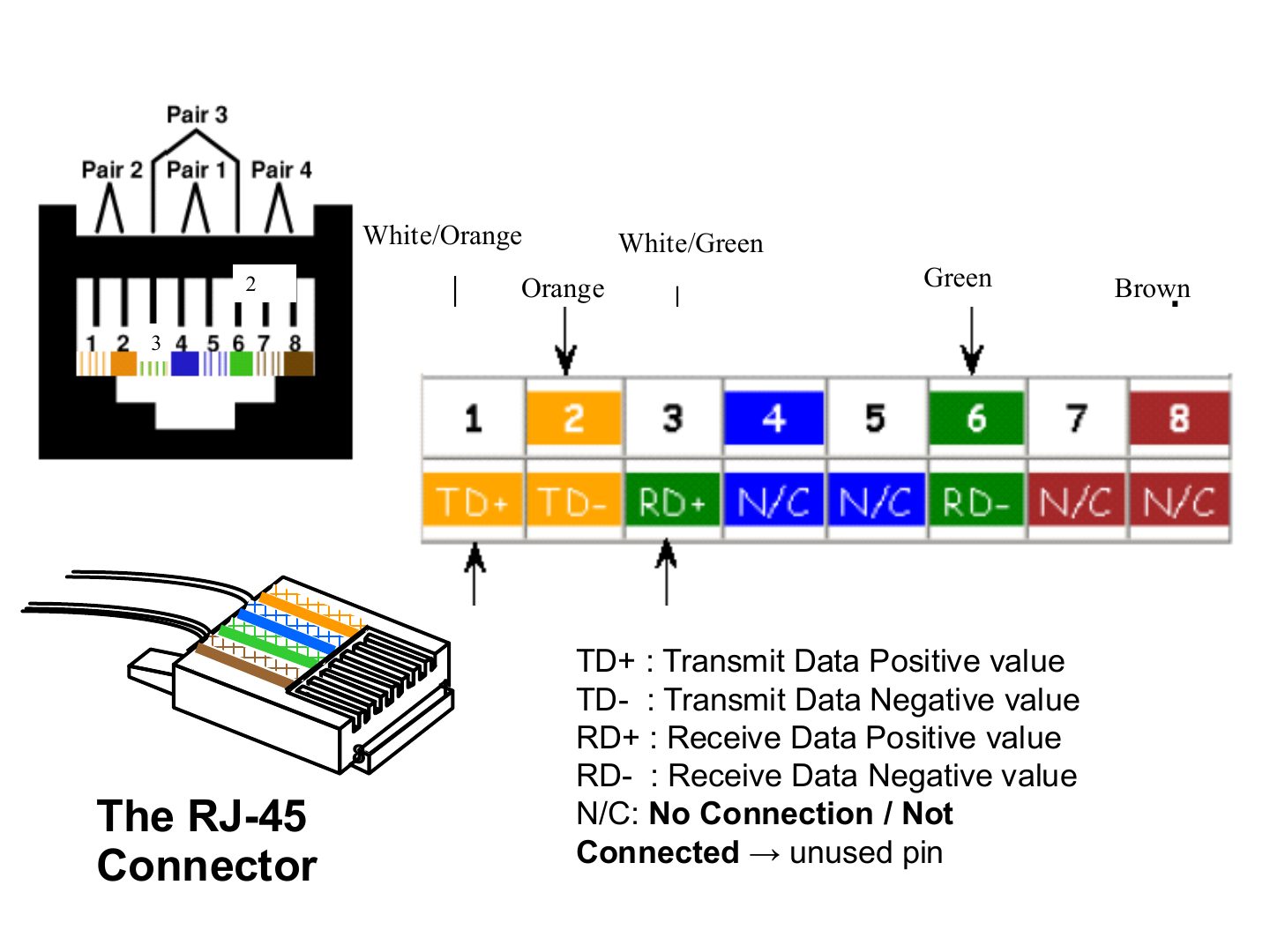
10/100 Ethernet uses only 4 pins: 1 & 2 transmit, 3 & 6 receive.
4, 5, 7, 8 are unused (Gigabit Ethernet uses all 8).
In 10/100 Ethernet, which RJ-45 pins are used to transmit?
Which pins receive data?
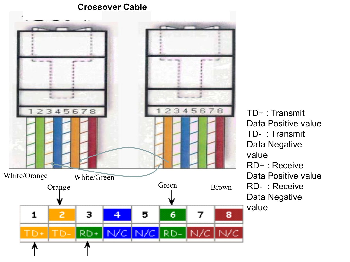
Crossover swaps 1↔3 and 2↔6, so TX on one side meets RX on the other.
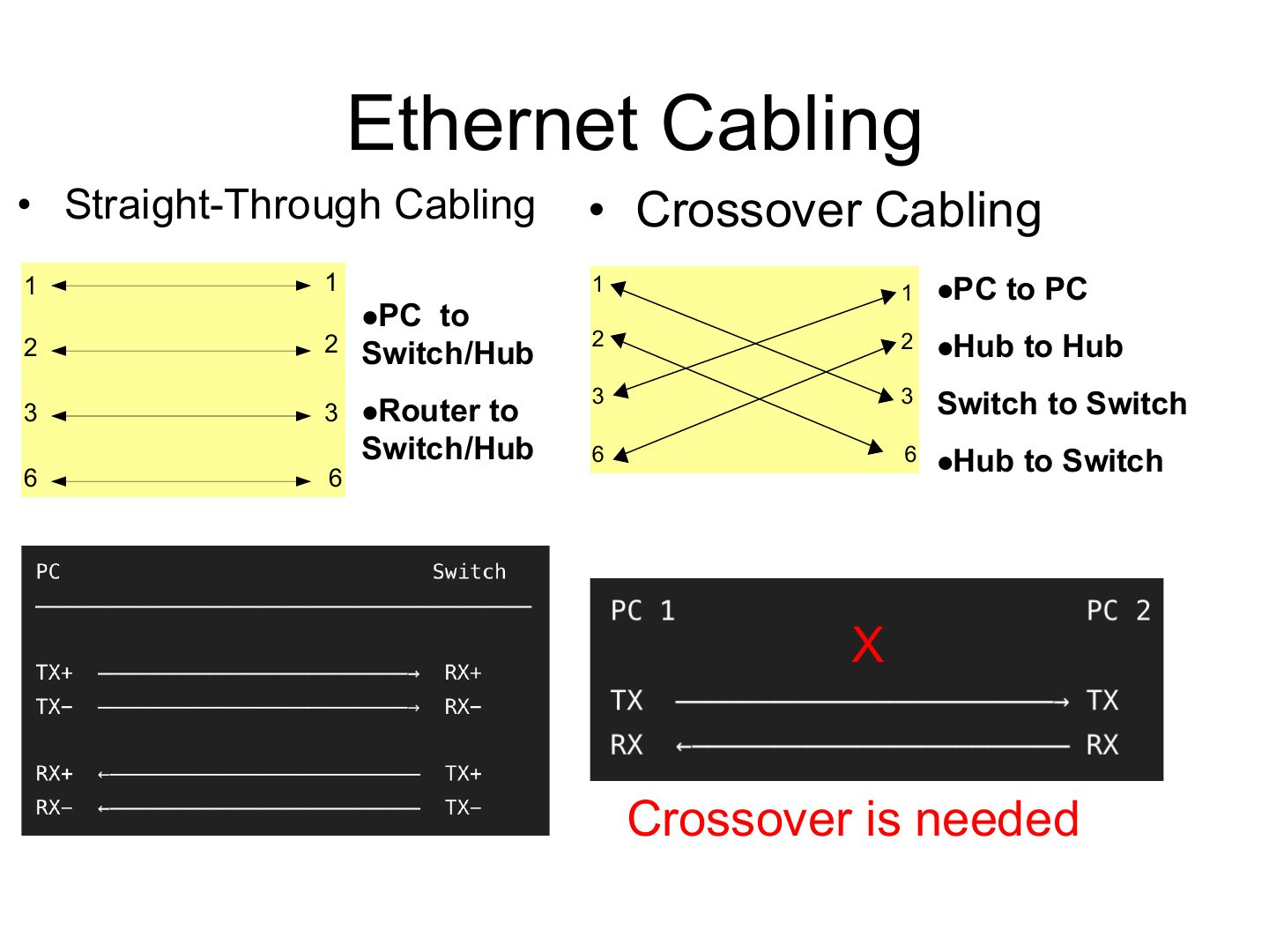
Different kinds of device (PC ↔ switch, router ↔ switch) → straight-through.
Same kind of device (PC ↔ PC, switch ↔ switch, hub ↔ hub, hub ↔ switch) → crossover, or TX meets TX.
Memory trick “Unlike → straight, like → cross.” (Router ↔ PC counts as “like”: both are end devices.)
Which cable connects two PCs directly?
Which cable connects a PC to a switch?
Two switches are connected with a straight-through cable.
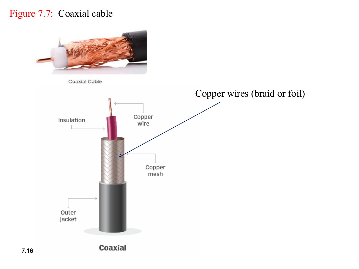
Coax = a central copper wire + an outer copper mesh as a shield. Used in cable TV and old bus Ethernet (10Base5, 10Base2).
Seen again Ch 4, slide 18: Which media each Ethernet generation uses
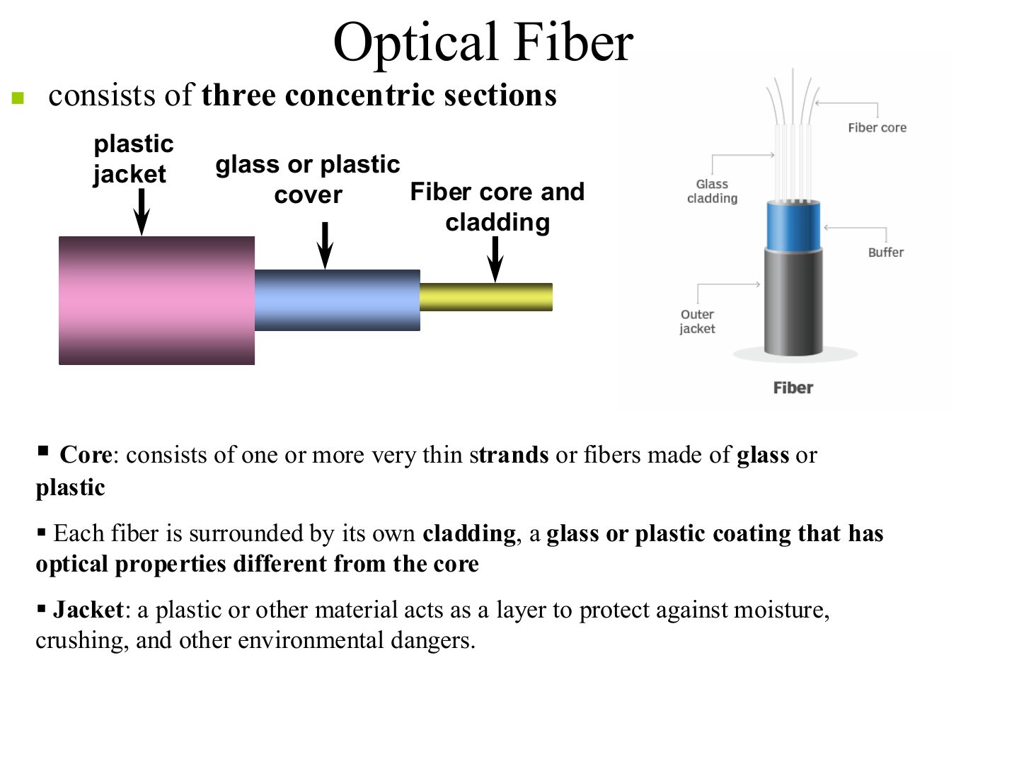
Core (carries the light) → cladding (different optical property, reflects the light back in) → jacket (protection).
The layer of a fiber that keeps the light inside the core is the:
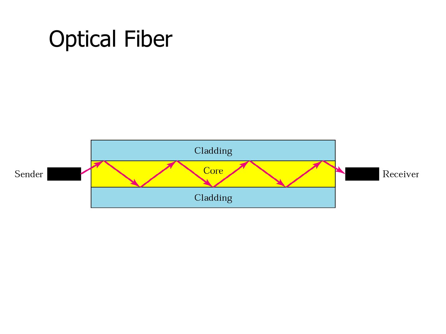
Light travels by reflecting off the core/cladding boundary.
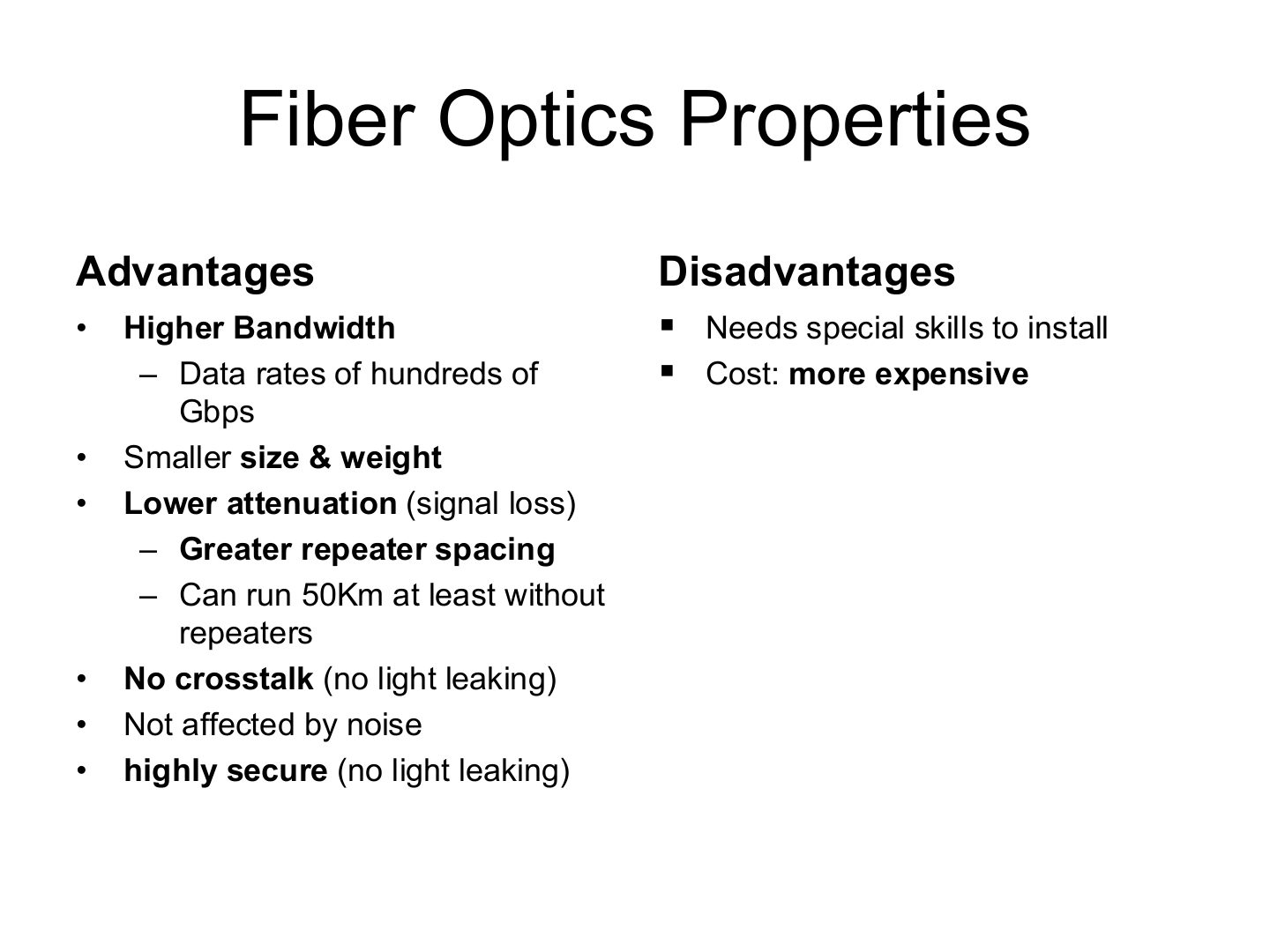
Trap Fiber is NOT cheaper or easier to install. Those are its two disadvantages.
Which is a disadvantage of fiber-optic cable?
Fiber-optic cable is not affected by electromagnetic noise.
Give three advantages of fiber over copper.
Higher bandwidth (hundreds of Gbps), lower attenuation so repeaters can be 50 km or more apart, immunity to noise and crosstalk, smaller size and weight, and better security because no light leaks out.
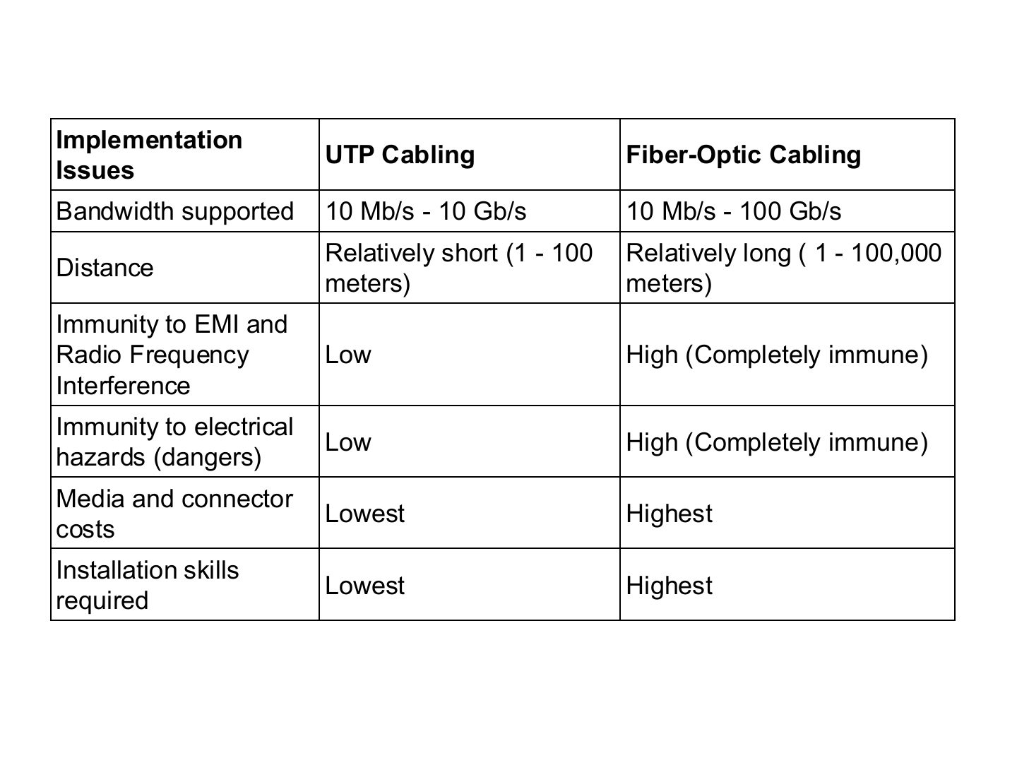
The maximum distance of a UTP segment in the table is about:
Two buildings 2 km apart must be linked, and a high-voltage line runs between them. Which cable?
Fiber. UTP only reaches about 100 m and is not immune to EMI or electrical hazards; fiber reaches tens of kilometres and is completely immune.
Three unguided media, from lowest to highest frequency.
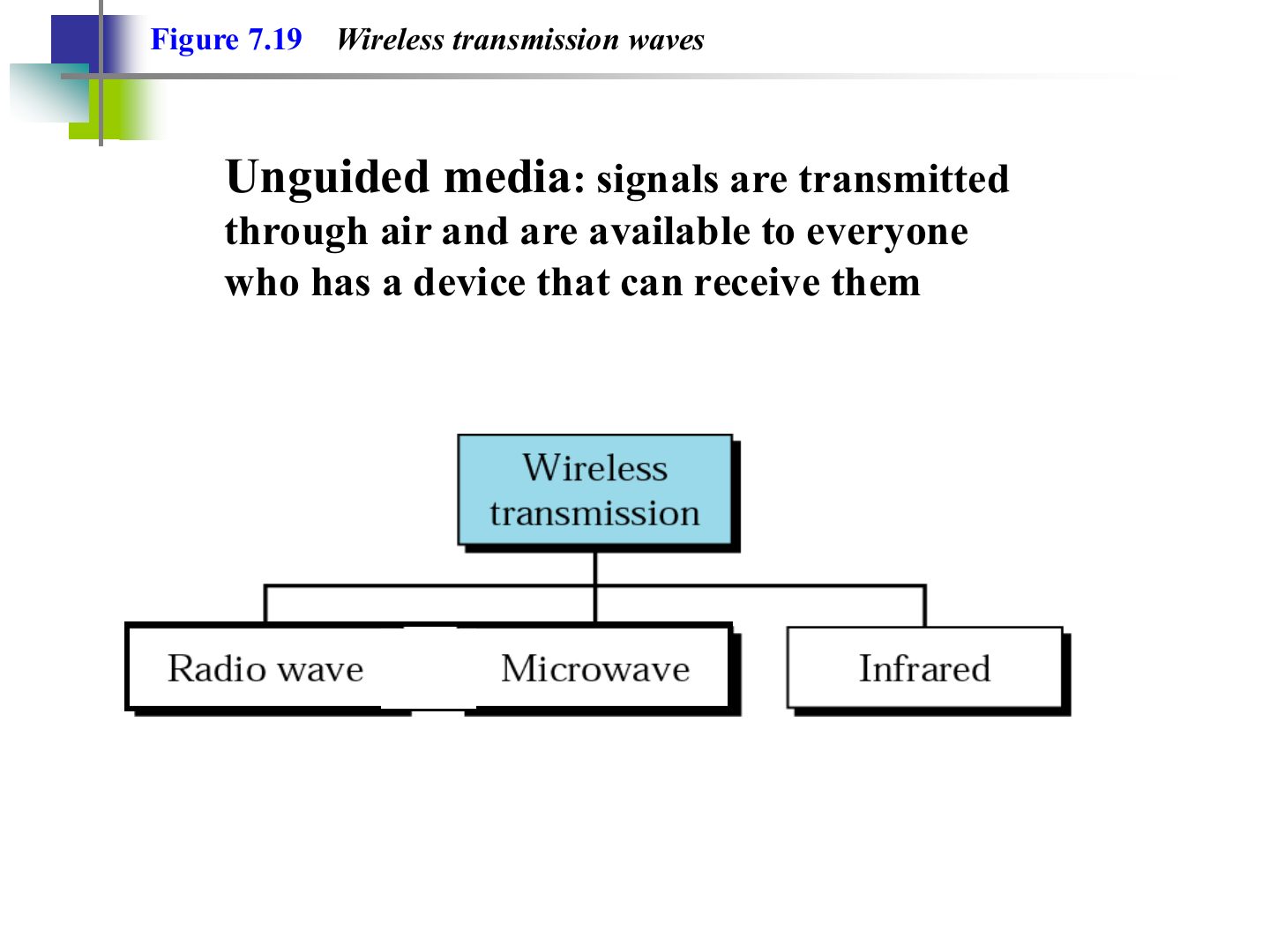
Unguided: the signal goes through the air and anyone with a receiver can pick it up (security matters).
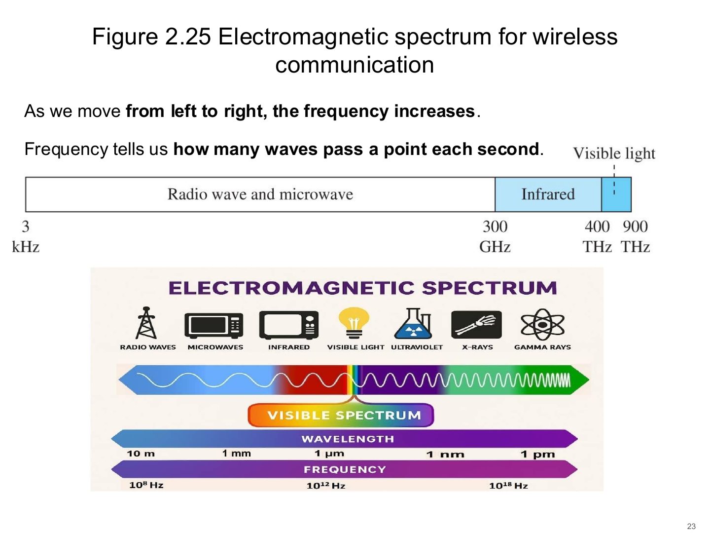
Radio < 300 MHz < microwave < 300 GHz < infrared < 400 THz < visible light.
Memory trick Order by frequency: Radio → Microwave → Infrared → Light (“Really Many Infrared Lights”).
Which has the highest frequency?
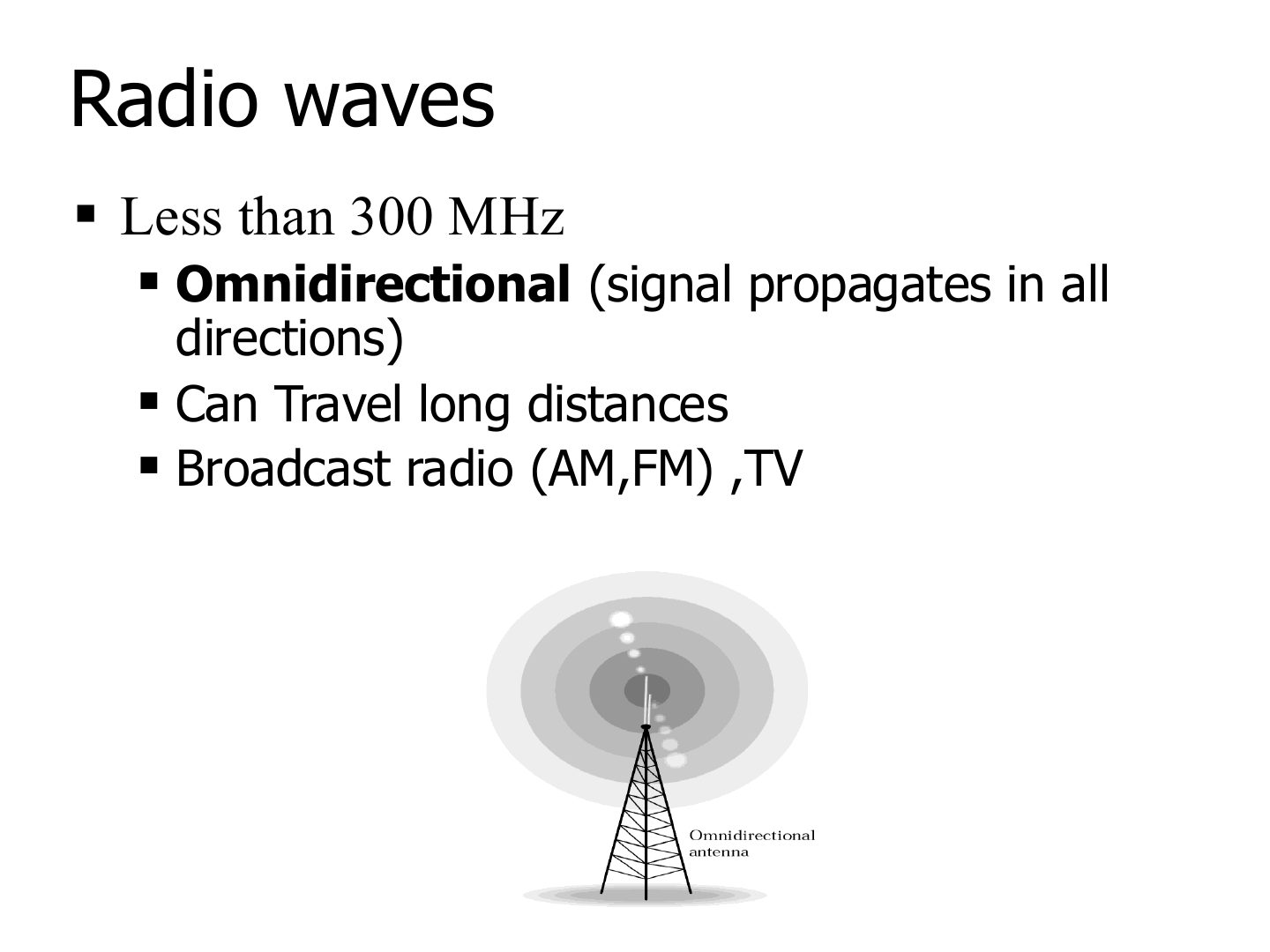
Radio: below 300 MHz, omnidirectional, long distances, passes through walls. Used for AM/FM and TV.
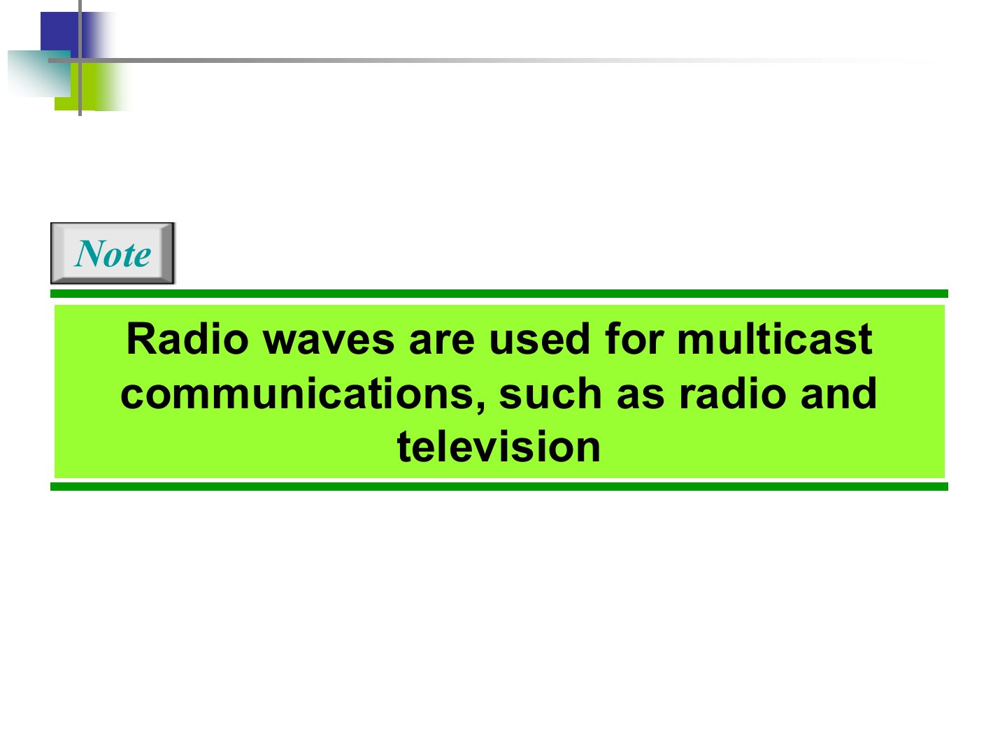
Radio = MULTICAST / broadcast (one sender, many receivers: radio and TV).
Radio waves are used for which type of communication?
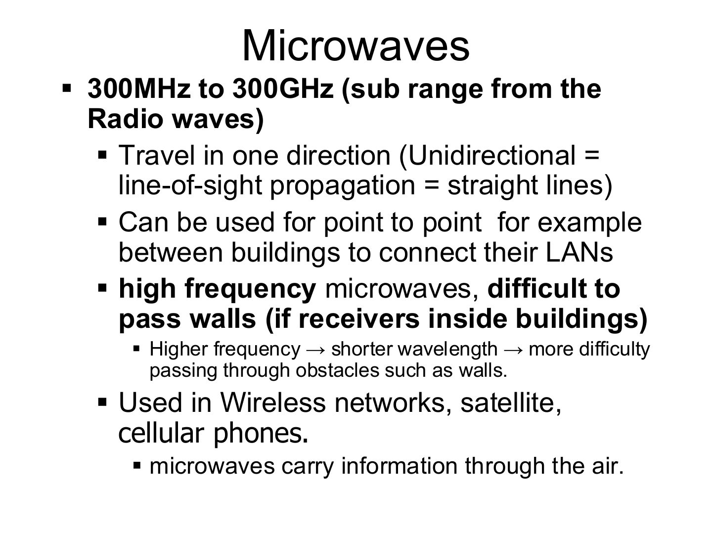
Microwave: 300 MHz – 300 GHz, unidirectional (line of sight), can link two buildings point to point.
Trap Radio is OMNIdirectional; microwave is UNIdirectional (line of sight).
Microwaves propagate:
Higher frequencies pass through walls more easily.
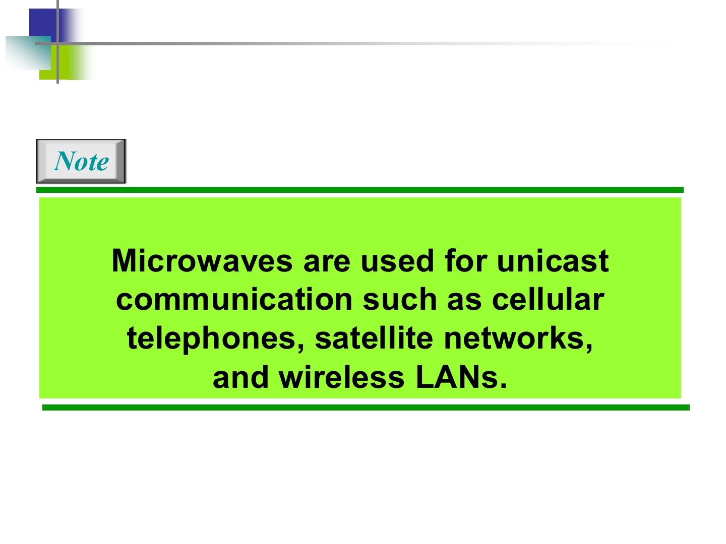
Cellular telephones and satellite networks mainly use:
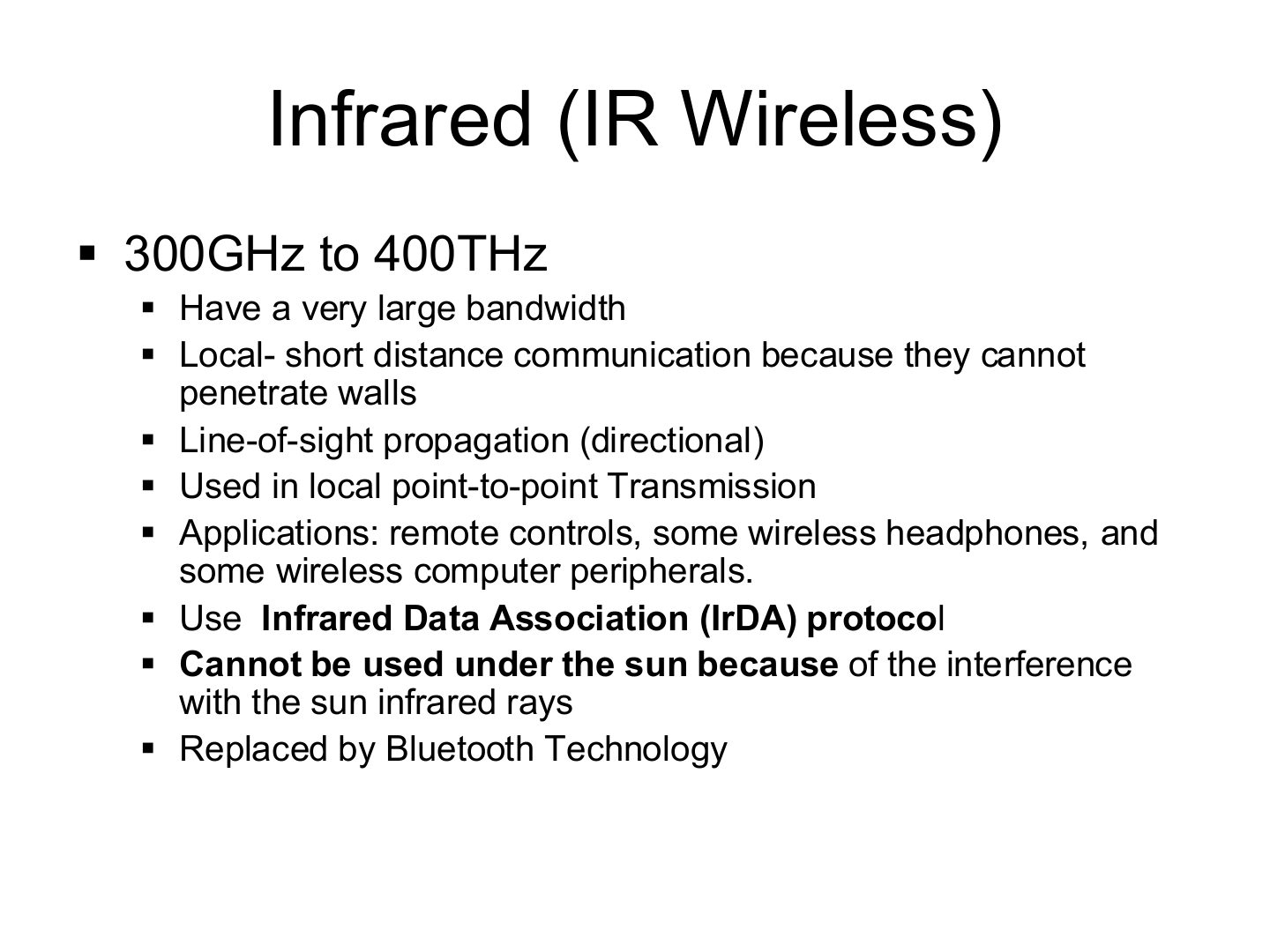
Infrared: 300 GHz – 400 THz, very large bandwidth, line of sight, short range (can’t pass walls).
Remote controls and some peripherals (IrDA protocol). Doesn’t work in sunlight. Mostly replaced by Bluetooth.
Why can’t infrared be used outdoors in the sun?
Which wireless medium cannot penetrate walls and is used in TV remote controls?
Compare radio waves, microwaves and infrared by direction and typical use.
Radio (< 300 MHz): omnidirectional, long range, multicast such as radio and TV. Microwave (300 MHz – 300 GHz): unidirectional line of sight, unicast such as cellular, satellite and wireless LANs. Infrared (300 GHz – 400 THz): line of sight, short range inside a room, such as remote controls.